Macro-Tech
®
602/1202/2402 Power Amplifiers
Page 9
Reference Manual
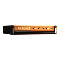
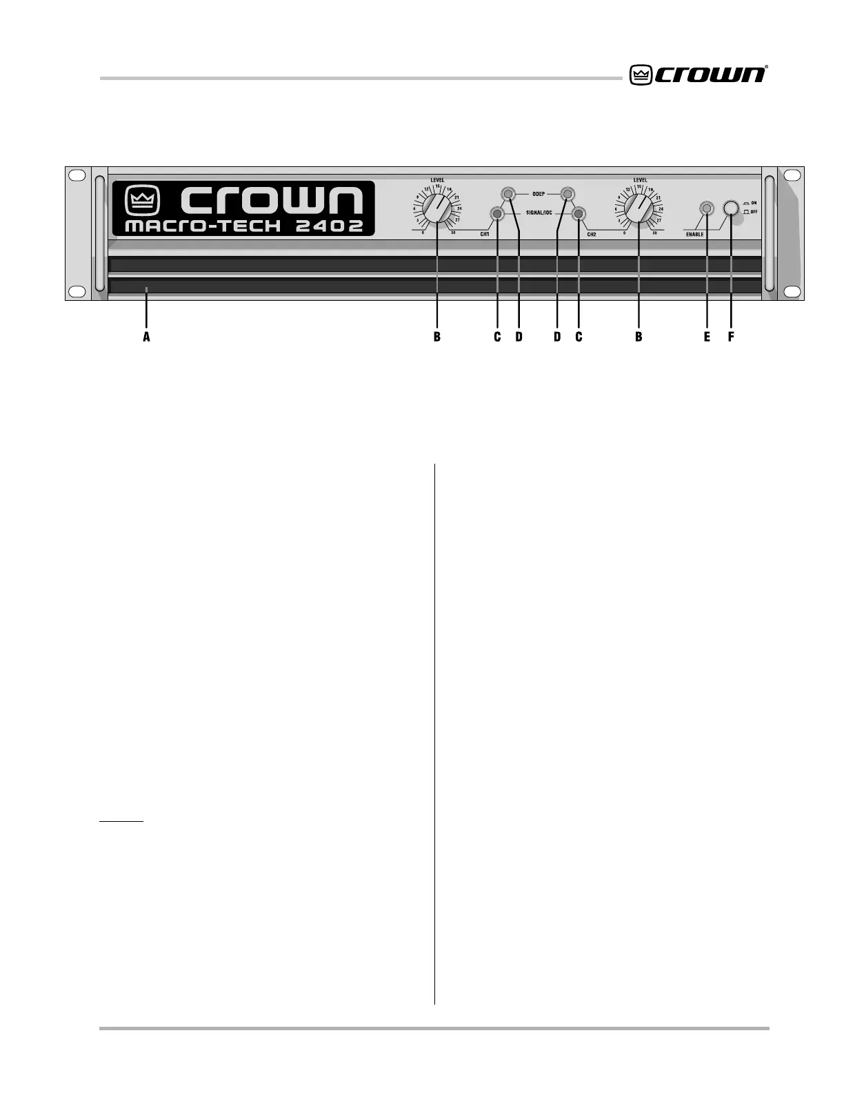
Fig. 2.1 Front Panel Controls & Indicators
2 Controls, Indicators &
Connectors
A. Dust Filters
The dust filters remove large particles from the air drawn
in by the cooling fan. Check the filters regularly to pre-
vent clogging. The filter elements can be easily re-
moved for cleaning by gently pulling them away from
the front panel (see Sections 3.2 and 4.5).
B. Level Controls
The output level for each channel is set with these con-
venient level controls mounted on the front panel. Each
level control has 31 detents for precise adjustment (see
Section 4.4). A security option is available to prevent
tampering (see Section 8.3).
C. Signal/IOC Indicators
These green multifunction indicators show signal pres-
ence and distortion for each channel. As signal pres-
ence indicators, they flash synchronously with the
output audio signals to show their presence. As IOC
(Input/Output Comparator) indicators, they flash
brightly with a 0.1 second hold delay if there is a differ-
ence of 0.05% or more between the input and output
signal waveforms. This provides
proof of distortion-free
performance
.
Note: The Channel 2 IOC indicator stays
on in Parallel-Mono mode (see Section 4.2).
D. ODEP Indicators
During normal operation of the ODEP (Output Device
Emulation Protection) circuitry, these amber indicators
glow brightly to show the presence of reserve thermal-
dynamic energy. They dim proportionally as energy re-
serves decrease. In the rare event that energy reserves
are depleted, the indicators turn off and ODEP propor-
tionally limits output drive so the amplifier can safely
continue operating even under severe conditions.
These indicators can also help identify more unusual
operating conditions (see Section 4.2).
E. Enable Indicator
This indicator lights when the amplifier has been “en-
abled” or turned on, and AC power is available (see
Section 4.2).
F. Enable Switch
This push button is used to turn the amplifier on and off.
When turned on, the output is muted for approximately
four seconds to protect your system from start-up tran-
sients. (This delay can be changed. Contact Crown’s
Technical Support Group for details.)
G. Power Cord
The power cord has an appropriate plug for the required
voltage. 120 VAC, 60 Hz North American Macro-Tech
602s and 1202s have 14 AWG line cords and NEMA 5-
15P plugs. Macro-Tech 2402s have 12 AWG line cords
and NEMA 5-20P plugs. International units are shipped
with an appropriate line cord and plug. See Section 7
for AC power usage.
H. Stereo/Mono Switch
The three operating modes of a Macro-Tech amplifier
are controlled by this switch. Stereo mode is used for
normal two-channel operation, Bridge-Mono mode is
used to drive a single channel with a load impedance of
at least 4 ohms, and Parallel-Mono mode is used to
 Loading...