page 9
MA 2402 Power Amplifier
Operation Manual
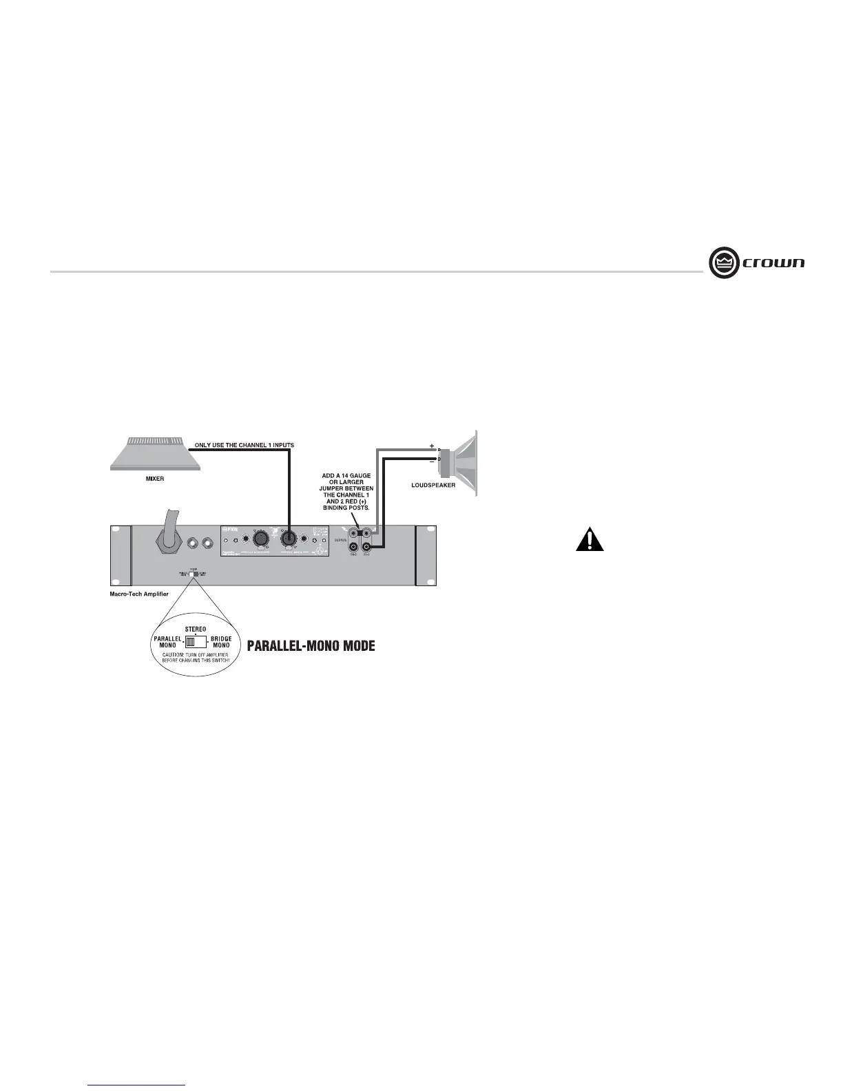
3.6.3 Parallel-Mono Mode
See Figure 3.8. Set the back panel
stereo/mono switch to Parallel-Mono.
INPUTS: Connect input wiring to Channel 1
only.
OUTPUTS: Add a 14 gauge (or larger) jumper
between the red(+) Channel 1 and Channel 2
binding posts. Connect the speaker positive (+)
lead to the Channel 1 red (+) terminal. Connect
the speaker negative (-) lead to the Channel 1
black (-) terminal.
Crown provides a reference of wiring pin assign-
ments for commonly used connector types in the
Crown Amplifier Application Guide.
NOTE: Use only the Channel 1 level
control.
CAUTION: Parallel-Mono wiring requires
installation of a jumper wire. Do not
switch to Stereo or Bridge-Mono mode
until this output jumper wire is removed.
NOTE: The Channel 2 IOC indicator will
remain lit when operating in
Parallel-Mono mode.
Figure 3.8
Parallel-Mono
Wiring
3 Setup
 Loading...