 Loading...
Do you have a question about the Cub Cadet 5254 and is the answer not in the manual?
Read and follow all instructions before starting. Only allow qualified individuals to operate the machine.
Operate up and down slopes, not across. Avoid turns and sudden movements. Do not operate on slopes exceeding 15 degrees.
Keep children away from the mowing area. Never assume children will remain where you last saw them. Remove key when unattended.
Disengage PTO, stop engine, and wait for PTO to stop before dismounting or disconnecting equipment.
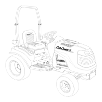
The ROPS must be maintained in functional condition. Use care when driving through low overhead spaces.
Use extreme care in handling gasoline. Keep tractor free of debris. Stop blades before cleaning or repairing.
Used to change direction of the tractor. Features hydraulic power steering.
Adjusts engine speed. Rotate rearward to increase speed.
Engages or disengages the Power Take-Off (PTO). Push top to engage, bottom to disengage.
Controls engine start, run, and off positions. Remove key when not in use.
Engages brakes and neutralizes transmission. Depress fully to activate safety interlock.
Controls reverse movement. Use caution when backing.
Controls forward movement. Speed depends on pedal depression.
Engages or disengages four-wheel drive for increased traction.
Raises and lowers three-point hitch lift arms.
Warns others when operating on or near roadways. Flashes when switch is on.
Reduces risk of injury in an overturn. Must be used with ROPS.
Selects high or low speed range for transmission. Must be stopped before shifting.
Allows PTO to operate in reverse. Use with extreme caution. Switch lights up when activated.
Engages the parking brake by pushing downward while brake pedal is depressed.
Engages differential lock for increased traction. Tractor steers with difficulty when engaged.
Activates flashing amber lights for visibility on or near roadways.
Turns headlights and instrument panel lights on or off.
Provides protection in an overturn. Protection is minimized if seat belt is not used.
Details operation of fuel gauge, tachometer, oil pressure, PTO, brakes, and coolant indicators.
ROPS and seat belts reduce injuries in an overturn. Use seat belt with ROPS, but not with folded/removed ROPS.
Prevents engine cranking/starting unless brake pedal is depressed and PTO is OFF.
Use clean, fresh, unleaded gasoline. Do not fill when engine is running or hot. Tighten fuel cap securely.
Proper care in first hours ensures optimal performance. Avoid full load immediately. Perform break-in maintenance.
Always sit in the operator's seat. Use choke as needed. Depress brake pedal or engage parking brake.
Disengage PTO, place throttle to slow, idle for one minute. Turn key to OFF and remove.
Avoid sudden starts/stops. Adjust seat. Use seat belt. Shift Hi/Lo range. Depress forward/reverse pedals.
Depress brake pedal, engage parking brake. Disengage PTO, idle engine, turn key off.
Control speed by depressing pedals. Pedals self-neutralize. Stop with brake pedal. Do not change direction while moving.
Selects high or low speed range for transmission. Must be stopped before shifting.
Operate up/down slopes, not across. Avoid turns. Shift to LOW speed and 4WD when descending.
Engages differential lock for increased traction. Tractor steers with difficulty when engaged.
Engages or disengages four-wheel drive. Stop before shifting. Use for slippery surfaces or slopes.
Raises and lowers attachments. Move lever to desired position. Float position locks lift.
Operator must be in seat. Move throttle to mid. Push PTO switch to engage. Use correct RPM range.
Allows PTO to operate in reverse. Use with extreme caution. Switch lights up when activated.
Use headlights for low light conditions. Depress top to turn on, bottom to turn off.
Activate flashing amber lights for visibility on or near roadways.
Attach implements. Disengage PTO, stop engine, set brake before connecting/disconnecting.
Adjust seat to most comfortable position using the single lever. Do not adjust while moving.
Adjust belt for snug fit. Reposition adjuster clip if needed for proper length.
Adjust RH adjustable lift link to level lower hitch links. Adjust upper hitch link length.
Check toe-in periodically. Readjust tie rod if necessary for proper alignment.
Check and adjust brake linkage to ensure proper brake operation. Measure gap between puck and disc.
Details lubricant type, capacity, API classification, temperature, viscosity, and description for various applications.
Chart detailing operations, service intervals (hours/before use/storage), and reference numbers.
Instructions for opening the tractor hood using latch release lever or bracket. Close hood firmly.
Battery posts contain lead. Wash hands. Handle acid with care. Never connect/disconnect charger clips while ON.
Steps to remove battery: open hood, remove holddown strap, disconnect cables (negative first), lift out battery.
Test battery voltage. Charge with 12-volt charger at max 10 amps. Use voltmeter readings for charge time.
Keep terminals clean. Protect against corrosion. Avoid tipping. Recharge before service.
Disconnect negative cable for storage. Keep clean, store with full charge. Recharge periodically.
Check for blown fuses if system malfunctions. Use same capacity fuse for replacement.
Replaces main fuse by raising hood, locating fuse holder, pulling fuse, and replacing with 30 Amp fuse.
Check instrument panel fuses (3 Amp). Replace blown fuses with same capacity.
Relays operate various functions. Check with dealer if circuits are not functioning properly.
Check oil level in sight glass when engine is stopped and tractor is level. Add oil if below sight glass.
Change hydro transmission and hydraulic system filters after first 25 hours due to break-in contaminants.
Stop engine, lower implement. Clean area around filter. Remove old filter, replace with new, tighten.
Stop engine, lower implement. Clean area around filter. Remove old filter, replace with new, tighten.
Change oil after 200 hours. Warm oil, drain, replace filters, refill with specified oil. Check for leaks.
Check oil levels after 50 hours. Unscrew fill plug/dipstick, wipe, reinsert, and read level.
Change oil after 300 hours. Warm oil, drain, refill with specified lube. Do not overfill.
Lubricate both ends of drive shaft every 50 hours using pressure gun and specified grease.
Lubricate both ends of FWD drive shaft every 50 hours using pressure gun and specified grease.
Retorque front and rear wheel lug nuts after 10 hours and every 100 hours (60-70 ft-lbs).
Check air pressure weekly or every 50 hours. Do not inflate over max pressure. Never reinflate flat tires.
Inspect ROPS for damage and loose fasteners every six months. Do not straighten or weld. Replace if damaged.
Prepare for storage: change oil/filter, treat fuel, charge battery, lubricate points, block tires.
Check oil/coolant levels, charge battery, inflate tires, start engine, run without load to check systems.
Explains emissions warranty coverage, owner responsibilities, and warranted parts.
Perform required maintenance, present engine for repairs, avoid abuse/neglect/improper maintenance.
Warrants engine free from defects for two years. Covers repair/replacement of warranted parts.
Warranty excludes misuse, neglect, lack of maintenance, improper repairs, non-genuine parts.
Liability limited to remedying defects by authorized dealer. No coverage for inconvenience or consequential damages.
Use care when servicing hot engine components. Place tractor on level surface, stop engine, remove key.
Keep radiator/cooler fins free of dirt/debris to prevent overheating. Keep muffler area clean.
Lift hood, flush screen with water. Blow debris from radiator fins with compressed air.
Check level before each use when engine is stopped and tractor is level. Keep between H and L marks.
Never overfill. Fill to FULL mark. Always check level before adding more oil.
Change after 8 hours and every 100 hours. Warm oil, drain via valve, replace filter, refill.
Check coolant level in overflow reservoir when engine is cold and tractor is level. Add coolant if low.
Check hoses for cracks, deterioration, and loose connections every 200 hours. Replace damaged hoses.
Drain coolant when cold. Reinstall drain plug. Refill with 50/50 antifreeze/water solution.
Check daily. Remove dirt/debris from housing. Replace filter element if dirty or damaged.
Wash foam precleaner every 25 hours. Wash in warm water with detergent. Allow to air dry. Do not apply oil.
Replace paper element every 300 hours or yearly. Check for dirt, tears, or damage. Do not use pressurized air.
Check plugs every 100 hours. Remove dirt, clean electrodes, inspect for damage, check gap (.030 inch).
Inspect filter periodically for residue or discoloration. Replace when dirty. Do not replace when hot.
Details manufacturer, horsepower, cylinders, bore, stroke, displacement, speeds, and capacities.
Specifies system type, thermostat opening, radiator cap pressure, and capacity.
Details charging system capacity, battery type, and starter motor type.
Specifies fuel tank capacity, type, filter type, and fuel pump type.
Details transmission type, drive, oil, capacity, shift range, and travel speeds.
Specifies type, control, pump capacity, and maximum pressure.
Details brake type and parking brake type.
Specifies steering type and turning radius.
Details PTO type, speed, shaft size, and horsepower at PTO.
Lists tire sizes for Turf and Ag front and rear applications.
Provides overall length, width, height, wheelbase, ground clearance, and weight.
Evaporative emission control system warranted for two years. Covers repair or replacement of defective parts.
Perform required maintenance, present engine for repairs, avoid abuse/neglect.
Warrants conformity with regulations and freedom from defects. Period begins on delivery date.
Covers tractors and attachments against defects for non-commercial use (2 years/1500 hrs) and commercial use (1 year/1500 hrs).
Present proof of purchase and maintenance records to local authorized dealer. Contact info provided.