4
RECOMMENDED OIL TYPE
Using the proper type and weight of oil in the crankcase is extremely important. Check the oil before
each use and change the oil regularly. Failure to use the correct oil, or using dirty oil, can cause
premature engine wear and failure.
Use a high-quality SAE 30 weight oil of API (American Petroleum Institute) service class.
ADDING OIL TO CRANKCASE: INITIAL USE
NOTE: This unit is shipped without oil. In order to avoid damage to the unit, put oil in the crankcase
before you attempt to start the unit.
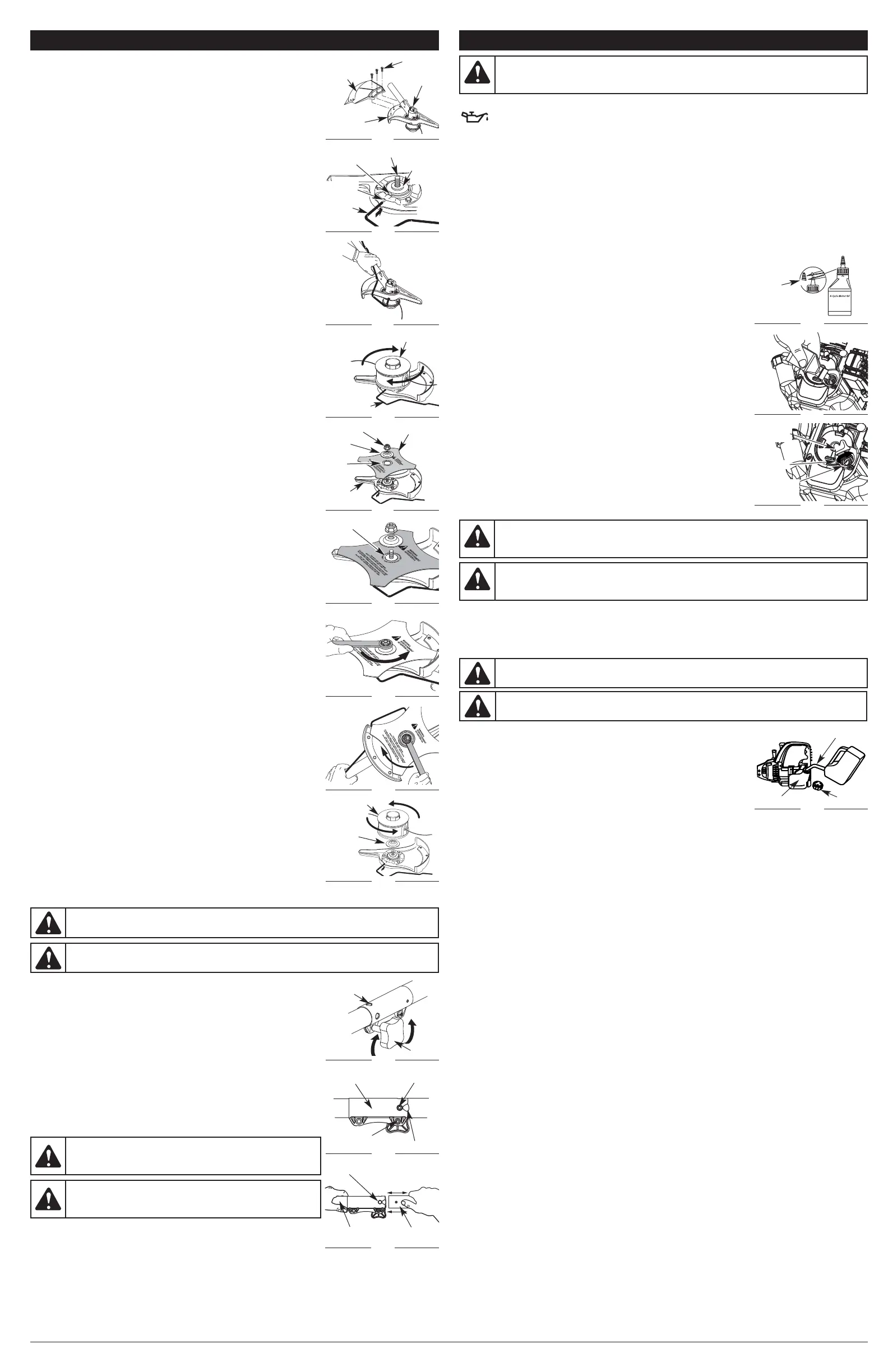
Your unit is supplied with one 3.04 fluid oz. (90 ml) bottle of SAE 30 oil (Fig. 16).
NOTE: Save the bottle of oil. It can be used to measure the correct amount during future oil changes.
See Changing the Oil.
1. Unscrew the top of the bottle of oil and remove the paper seal covering the opening. Replace the top.
Next, cut the tip off the funnel spout (Fig. 16).
2. Tip unit so that the back of the engine is facing up in a vertical position.
3. Remove the oil fill plug from the crankcase (Fig. 18).
4. Pour the entire bottle of oil into the oil fill hole (Fig. 17).
NOTE: Never add oil to the fuel or fuel tank.
5. Wipe up any oil that may have spilled and reinstall the oil fill plug.
Check oil before each use and change as needed. Refer to Checking the
Oil Level.
RECOMMENDED FUEL TYPE
Old fuel is the primary reason for improper unit performance. Be sure to
use fresh, clean, unleaded gasoline.
NOTE: This is a four cycle engine. In order to avoid damage to the unit, do
not mix oil with gasoline.
Definition of Blended Fuels
Today's fuels are often a blend of gasoline and oxygenates such as
ethanol, methanol or MTBE (ether). Alcohol-blended fuel absorbs water. As
little as 1% water in the fuel can make fuel and oil separate or form acids
when stored. Use fresh fuel (less than 30 days old), when using alcohol-
blended fuel.
Using Blended Fuels
If you choose to use a blended fuel, or its use is unavoidable, follow
recommended precautions:
• Always use fresh unleaded gasoline
•Use the fuel additive STA-BIL® or an equivalent
• Drain tank and run the engine dry before storing unit
USING FUEL ADDITIVES
The use of fuel additives, such as STA-BIL® Gas Stabilizer or an equivalent, will inhibit corrosion and
minimize the formation of gum deposits. Using a fuel additive can keep fuel from forming harmful
deposits in the carburetor for up to six (6) months. Add 0.8 oz. (23 ml) of fuel additive per gallon of fuel
according to the instructions on the container. NEVER add fuel additives directly to the unit's gas tank.
FUELING THE UNIT
1. Remove the fuel cap (Fig. 19).
2. Place the gas container’s spout into the fill hole on the fuel tank (Fig.
19) and fill the tank.
NOTE: Do not overfill the tank.
3. Wipe up any gasoline that may have spilled.
4. Reinstall the fuel cap.
5. Move the unit at least 30 ft. (9.1 m) from the fueling source and site
before starting the engine.
NOTE: Dispose of the old gasoline in accordance with federal, state and local regulations.
Gas Can Spout
Fig. 19
WARNING:
Remove fuel cap slowly to avoid injury from fuel spray. Never operate the unit without
the fuel cap securely in place.
Fuel Tank
Fuel Cap
WARNING:
DO NOT USE E85 FUEL IN THIS UNIT. It has been proven that fuel
containing greater than 10% ethanol will likely damage this engine and void the warranty.
OIL AND FUEL INFORMATION
WARNING:
Overfilling oil crankcase may cause serious personal injury. Check and
maintain the proper oil level in the crank case; it is important and cannot be overemphasized.
Check the oil before each use and change it as needed. See Changing the Oil.
Funnel
Spout
Fig. 16
Fig. 18
Oil Fill
Plug
O-Ring
Fig. 17
Oil Fill
Hole
WARNING:
Add fuel in a clean, well ventilated outdoor area. Wipe up any spilled fuel
immediately. Avoid creating a source of ignition for spilt fuel. Do not start the engine until
fuel vapors dissipate.
WARNING:
Gasoline is extremely flammable. Ignited vapors may explode. Always stop
the engine and allow it to cool before filling the fuel tank. Do not smoke while filling the tank.
Keep sparks and open flames at a distance from the area.
REMOVE AND INSTALL THE CUTTING ATTACHMENT SHIELD
Remove the cutting attachment shield when using the unit as a
brushcutter
Remove the cutting attachment shield from the shield mount by removing
the three (3) screws with a flat blade screwdriver (Fig. 4). Store parts for
future use.
Install the cutting attachment shield when using the unit as a grass
trimmer
Install the cutting attachment shield on the shield mount by inserting the
three (3) screws into the shield mount. Tighten securely with a flat blade
screwdriver (Fig. 4).
REMOVE THE CUTTING ATTACHMENT AND INSTALL THE CUTTING
BLADE
NOTE: To make cutting blade removal and installation easier, place the unit
on the ground or on a work bench.
Remove the Cutting Attachment Shield
See Remove and Install the Cutting Attachment Shield.
Remove the Cutting Attachment
1. Align the shaft bushing hole with the locking rod slot and insert the
locking rod into the shaft bushing hole (Fig. 5).
2. Hold the locking rod in place by grasping it next to the boom of the unit
(Fig. 6).
3. While holding the locking rod, remove the cutting attachment by turning
it clockwise off of the output shaft (Fig. 7). Store the cutting attachment
for future use.
NOTE: The blade retainer under the cutting attachment will be used when
installing the cutting blade.
Install the Cutting Blade
4. Place the cutting blade on the output shaft bushing (Fig. 8).
5. Make sure that the cutting blade is centered on the pilot step and sitting
flat against the output shaft bushing (Fig. 9).
6. Align the shaft bushing hole with the locking rod slot and insert the
locking rod into the bushing hole (Fig. 5).
7. Put the blade retainer and nut on the output shaft. Make sure that the
blade is installed correctly.
8. Tighten nut counterclockwise against the blade while holding the
locking rod:
• If using a torque wrench and a 13 mm socket tighten to: 325 - 335 in•lb,
27 - 28 ft.•lb, 37 - 38 N•m.
• Without a torque wrench, use a 13 mm closed-end or socket wrench,
turning the nut until the blade retainer is snug against the shaft bushing.
Make sure that the blade is installed corr
ectly, then rotate the nut an
additional 1/4 to 1/2 turn counterclockwise (Fig. 10).
9. Remove the locking rod from the locking rod slot.
REMOVE THE CUTTING BLADE AND INSTALL THE CUTTING
ATTACHMENT
Remove the Cutting Blade
1. Align the shaft bushing hole with the locking rod slot and insert the
locking rod into the bushing hole (Fig. 5).
2. Hold the locking rod in place by grasping it next to the boom of the unit
(Fig. 11).
3. While holding the locking rod, loosen the nut on the blade by turning it
clockwise with a 13 mm closed-end or socket wrench (Fig. 11).
4. Remove the nut, blade retainer and blade. Store the nut and blade
together for future use in a secure place. Store out of children’s reach.
Install the Cutting Attachment
5. Align the shaft bushing hole with the locking rod slot and insert the
locking rod into the shaft bushing hole (Fig. 5). Place the blade retainer
on the output shaft with the flat surface against the output shaft
bushing (Fig. 12). Screw the cutting attachment counterclockwise onto
the output shaft. Tighten securely.
NOTE: The blade retainer must be installed on the output shaft in the
position shown for the cutting attachment to work correctly.
6. Remove the locking rod.
7. Install the cutting attachment shield. Refer to Remove and Install the
Cutting Attachment Shield.
Screws (3)
Cutting
Attachment
Shield
Fig. 4
Gearbox
Shield
Mount
Shaft
Bushing Hole
Output Shaft
Output
Shaft
Bushing
Fig. 5
Fig. 6
Cutting Attachment
Locking Rod
Fig. 7
Nut
Cutting Blade
Fig. 8
Blade
Retainer
Shield
Mount
Pilot
Hole
Pilot
Step
Fig. 9
Fig. 10
Clockwise
Fig. 11
Cutting
Attachment
Fig. 12
Blade
Retainer
ASSEMBLY INSTRUCTIONS
Locking
Rod Slot
Locking
Rod
OPERATING THE COUPLER
The coupler enables the use of various optional attachments.
NOTE: To make installing or removing the attachment easier, place the
unit on the ground or on a work bench.
Installing the Attachment
NOTE: Remove the protective cap and gray spacer from the upper and
lower shafts prior to assembling the attachment.
1. Turn the knob counterclockwise to loosen (Fig. 13).
2. While firmly holding the attachment, push it straight into the coupler
until the release button snaps firmly into the primary hole (Fig. 15).
NOTE: Aligning the release button with the guide recess will help
installation (Fig. 14).
3. Turn the knob clockwise to tighten (Fig. 13).
NOTE: Do not tighten the nut (Fig. 14).
For decorative edging with a string trimmer attachment, lock the release
button into the 90° edging hole (Fig. 13).
Removing the Attachment
1. Turn the knob counterclockwise to loosen (Fig. 13).
2. Press and hold the release button (Fig. 14).
3. While firmly holding the upper shaft housing, pull the attachment straight out of the coupler (Fig. 15).
WARNING:
Before using any attachment, read and understand the manual that came
with the attachment. Follow all safety information contained within.
CAUTION:
Before operating the unit, make sure the release
button is fully snapped into the primary hole (Fig. 15) and the
knob (Fig. 13) is securely tightened.
WARNING:
To avoid serious personal injury and damage to the unit, shut the unit off
before removing or installing an attachment.
CAUTION:
The release button should be snapped into the
primary hole only. Using the wrong hole could lead to personal
injury or damage to the unit.
Knob
Fig. 13
90˚ Edging Hole
(Trimmer Only)
Upper Shaft
Housing
Fig. 15
Lower Shaft
Housing
Primary Hole
Guide Recess
Fig. 14
Release Button
Coupler
Nut
 Loading...