ASSEMBLY
6
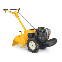
Fig. 1
Wheel Support Bracket
INSTALLING AND ADJUSTING THE WHEEL ASSEMBLY
Installing the Wheel Assembly
1. Insert the wheel assembly into the wheel bracket. The "J" shape
of the wheel assembly should point away from the unit (Fig. 1).
2. Align the hole in the wheel bracket with the desired hole in the
wheel assembly (Fig. 1).
3. Insert the clevis pin through the aligned holes (Fig. 1).
4. Insert the cotter pin into the clevis pin (Fig. 1).
NOTE: It may be necessary to adjust the position of the wheel
assembly before using the unit.
Adjusting the Wheel Assembly
1. Remove the cotter pin from the clevis pin (Fig. 1).
2. Remove the clevis pin from the wheel bracket and wheel
assembly (Fig. 1).
3. Align the hole in the wheel bracket with the desired hole in the
wheel assembly (Fig. 1).
NOTE: Moving the wheel assembly down will raise the wheel height.
Moving the wheel assembly up will lower the wheel height.
4. Insert the clevis pin through the aligned holes (Fig. 1).
5. Insert the cotter pin into the clevis pin (Fig. 1).
WARNING:
To prevent serious personal injury, the wheel
assembly must be installed when operating the unit.
WARNING:
To avoid injury from the tines, wear heavy
gloves and a long sleeve shirt when installing the wheel
assembly.
INSTALLING THE HANDLEBARS
Perform the following steps for both handlebars:
1. Align the hole in the handlebar with the hole in the lower handle
(Fig. 2).
NOTE: Take care not to pinch the throttle cable or switch wires
when positioning the handlebars (Fig. 3).
2. Insert a bolt through the aligned holes (Fig. 2).
3. Place a washer onto the bolt (Fig. 2).
4. Place a handlebar knob onto the bolt (Fig. 2).
5. Tighten the handlebar knob to secure the handlebar in place
(Fig. 3).
NOTE: Do not over tighten the knobs.
6. Readjust the throttle cable and switch wires so they are smooth
and tight against the handlebar assembly. This will help prevent
them from catching or snagging during normal operation.
Clevis Pin
Cotter Pin
Wheel Assembly
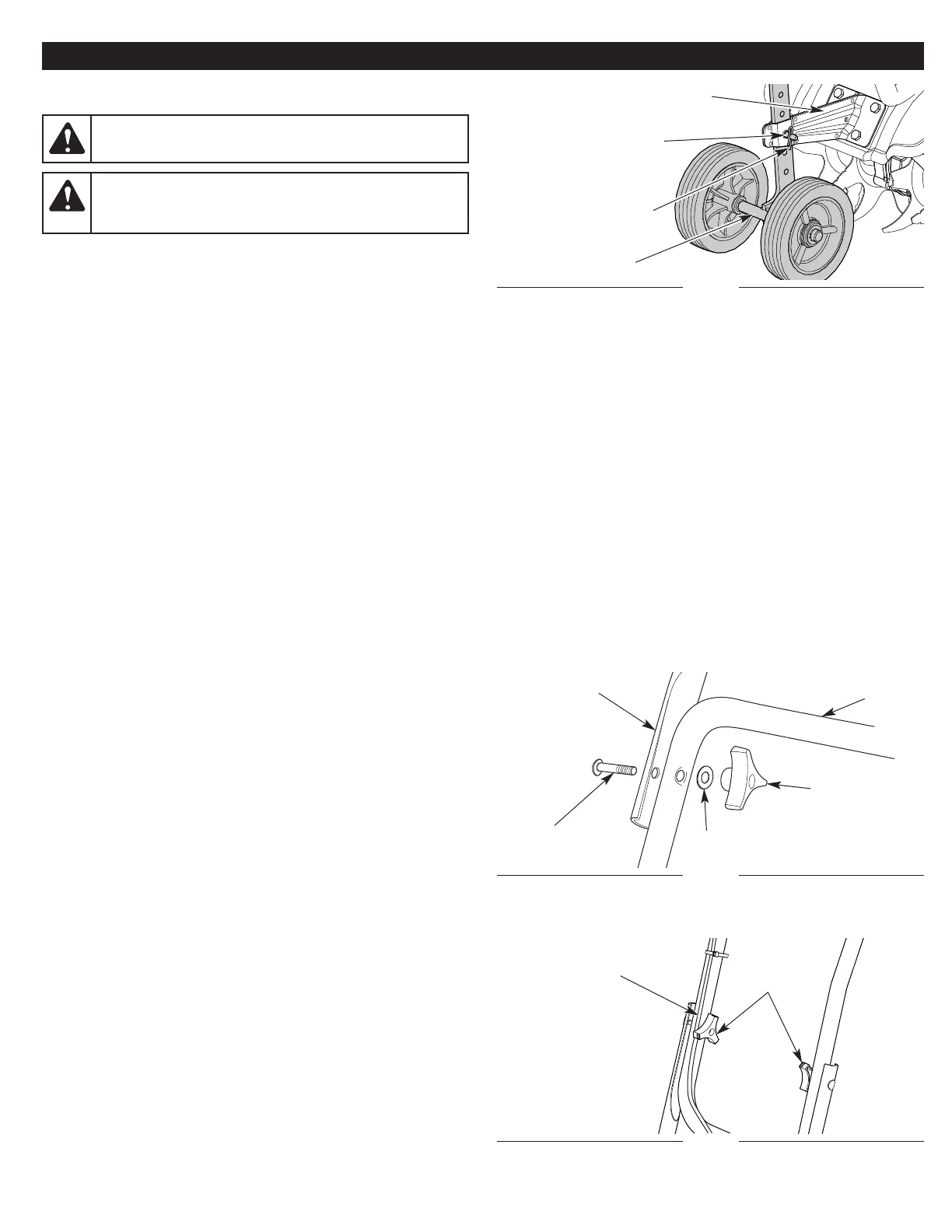
Fig. 2
Handlebar
Knob
Fig. 3
Throttle Cable
and Switch Wires
Handlebar
Knobs
Bolt
Lower
Handle
Washer
Handlebar
 Loading...