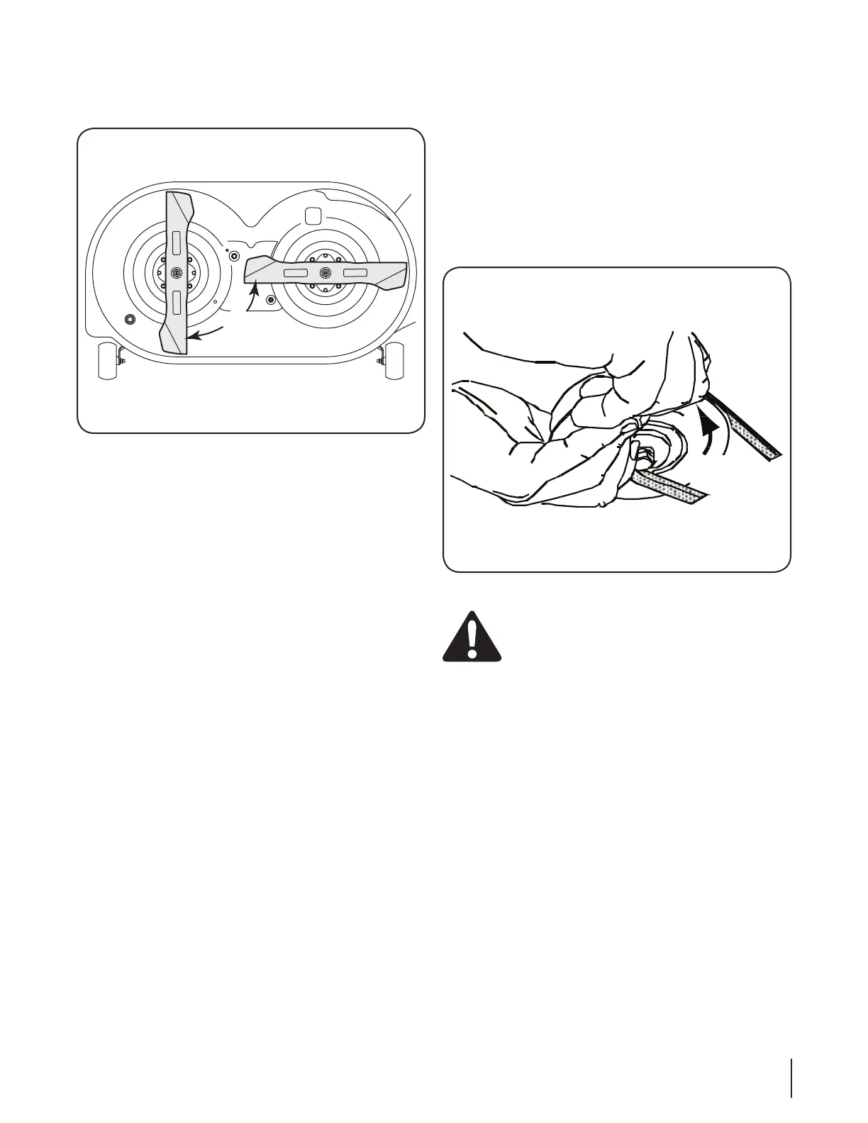
If the timing belt was installed correctly and the timing
arrows were positioned as shown in Fig. 7-6, the cutting
blades should be in the position shown in Fig. 7-7.
re-install the deck as described in “Re-installing the Cutting
Reinstalling the Cutting Deck
There are two methods for reinstalling the mower deck on the
to relieve enough belt tension to allow the belt to be placed
method is difficult, we recommend using the second method of
Install the cutting deck as follows:
From the right side of the tractor, slide the deck under the
tractor and align the rear deck hanger brackets with the
deck lift arms.
Slide the deck forward and place the deck front hanger rod 2.
into the slots of the deck front hanger bracket. Then slide
the deck rearward so that the front hanger rod is at the
front of the slots.
Using the deck lift lever, lower the deck lift arms. From
either side of the tractor, pull the support pin in the deck
rear hanger bracket outward, align the deck lift arm hole
with the deck support pin and release the pin so that it
goes through the deck lift arm. Repeat on the other side of
the tractor to secure the deck.
After first making sure the deck belt is properly engaged in 4.
all of the deck pulleys, route the deck belt forward through
pulley on the bottom of the engine.
Using the deck lift handle, raise the deck to the position 5.
that gives you the most horizontal run of the belt between
engine.
Sitting in front of the tractor, facing rearward, make certain 6.
the belt is not twisted; then reach beneath the tractor to
NOTE: References to left and right are from the front of the
tractor in the following instructions.
7.
While holding the belt and pulley together, rotate the 8.
pulley to the left. Continue holding and rotating the pulley
Fig. 7-8.
Use caution to prevent pinching your
Checking the Cutting Blade Timing
During normal operation the timing of the cutting blades can
be altered by abnormal loads on one, or both, cutting blades.
Regularly check the timing arrows on the spindle assemblies to
make certain they are 90° from each other.
If the timing arrows are not 90° from each other, proceed as
follows:
Remove the deck from the tractor. Remove the idler
bracket backstop. Refer to Figure 7-5.
2.
on the timing belt, and reposition the drive pulley and/or
timing pulley to achieve the 90° orientation of the timing
arrows.
Re-install the idler bracket backstop and position so that
there is a ⁄
Tighten the hex screw and flange lock nut to secure in the
adjusted position.
27se c t i O n 7 — se r v i c e

 Loading...