D-Link Switch User Manual
5
Hardware Installation
This chapter provides installation information for the D-Link DGS-1008P.
Installation Precautions
For safe switch installation and operation, it is recommended to:
Visually inspect the DC power jack and make sure that it is fully secured to the power adapter.
Make sure that there is proper heat dissipation and adequate ventilation around the switch.
Install the Switch in a site free from strong electromagnetic sources, vibration, dust, and direct
sunlight.
Not place heavy objects on the Switch.
Grounding the Switch
This section describes how to connect the Switch to ground. It is necessary to complete this procedure before
powering on the Switch.
Required Tools and Equipment
‧ One ground screw (attached to the back panel).
‧ Ground cable (not included in the accessory kit): The grounding cable should conform to local and national
installation requirements. Depending on the power supply and system, a 12 to 6 AWG copper conductor
is required for a US installation. Commercially available 6 AWG wire is recommended. The length of the
cable depends on the proximity of the Switch to proper grounding facilities.
‧ A screwdriver (not included in the accessory kit).
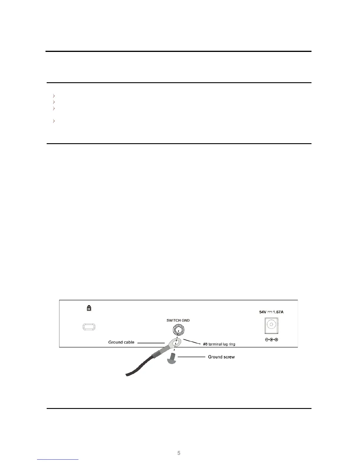
The following steps explain the procedure for connecting the Switch to a protective ground:
1. Verify that the system is powered off.
2. Use the ground cable to place the #8 terminal lug ring on top of the ground screw opening, as seen in
the figure below.
3. Insert the ground screw into the ground screw opening.
4. Using a screwdriver, tighten the ground screw to secure the ground cable to the Switch.
5. Attach the terminal lug ring at the other end of the grounding cable to an appropriate grounding stud or
bolt on the rack where the Switch is installed.
6. Verify that the connections from the ground connector on the Switch to the rack are securely attached.
Figure 4 – Attaching a Grounding Cable
Attaching the Rubber Pads
The DGS-1008P comes with a strip with 4 adhesive rubber pads to place on the bottom of the device to prevent
the Switch from damaging the surface it is placed on. This allows the Switch to be placed on virtually any flat
 Loading...