5
ADJUSTMENTS
E-F BALANCE ADJUSTMENT
1. Connect oscilloscope to test point TP502 and TP503
on CD PCB.
2. Press power switch on.
3. Put test disc(TCD-781) in and press play button then
pause button.
4. Pressing Fast Forward button, adjust RV502 to get
that the oscilloscope waveform is symmetrical on the
bottom in relation to 0V, and check this level.
* Design and specifications may be subject to change without notice.
3. TAPE SECTION
Test Tape be used
HEAD ADJUSTMENT (AZIMUTH)
1. 10KHz test tape(example: MTT-114N) must be used for this adjustment.
2. Connect to VTVM or oscilloscope to the headphone jack or speaker terminal.
3. Press the play button.
4. Adjust the azimuth by using a screw driver to maintain the max. L&R output voltage.
5. Adjust tape A(1), tape B(2) respectively, Please secure the azimuth position by using locking paint.
RECORDING BIAS OSCILLATOR FREQUENCY ADJUSTMENT
1. Connect the frequency counter to TP603, GND.
2. Press the REC button.
3. Adjust L603 to obtain 80 KHz
±
100Hz
Tape Contents Use
MTT-111N 3 KHz Tape Speed Adjustment
MTT-114N 10 KHz Head Azimuth Adjustment
MTT-5511 Blank Record Frequency Property
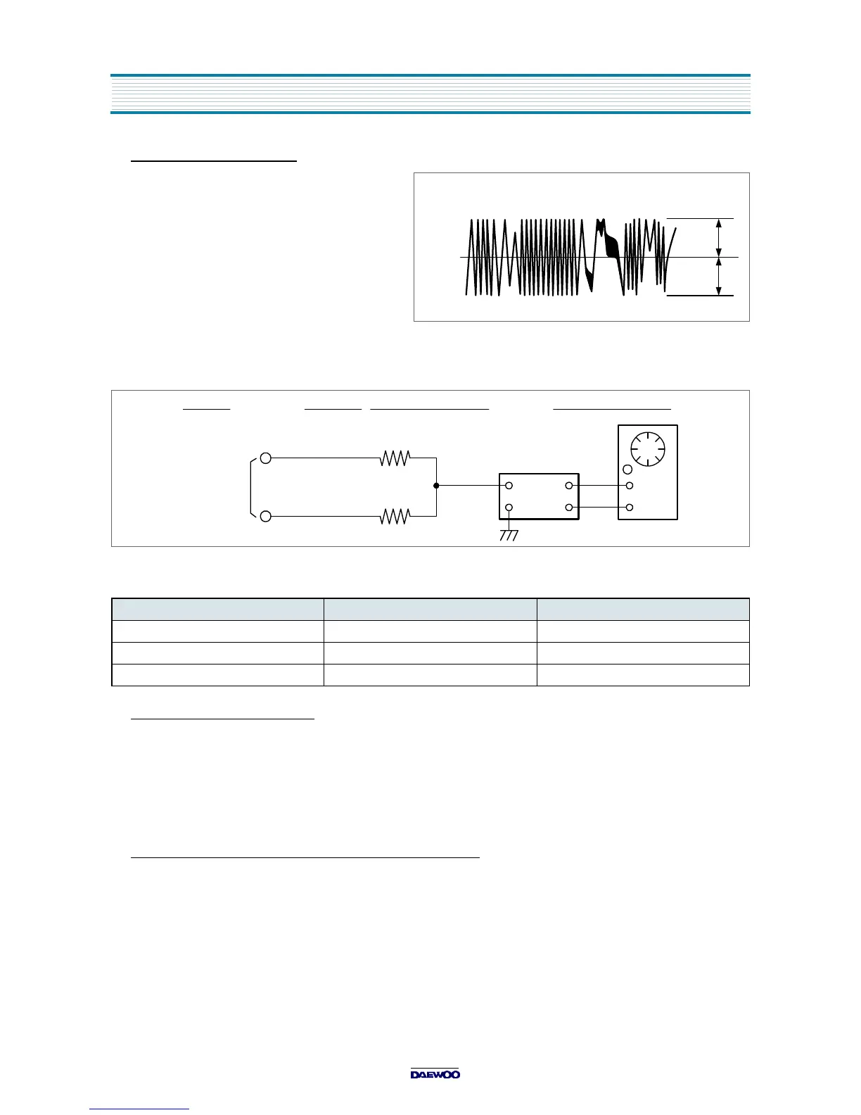
Traverse Waveform
A
B
0V
VTVM
Scope
R-CH
L-CH
47 kohm
47 kohm
Input Level
Measurement
Point
Input Point
 Loading...