EasyManua.ls Logo

Daewoo AMI-960 User Manual

Daewoo AMI-960
125 pages
To Next Page IconTo Next Page
To Previous Page IconTo Previous Page
Page #41 background imageLoading...
Page #41 background image
Question and Answer IconNeed help?

Do you have a question about the Daewoo AMI-960 and is the answer not in the manual?

Daewoo AMI-960 Specifications

General IconGeneral
BrandDaewoo
ModelAMI-960
CategoryStereo Receiver
LanguageEnglish

Summary

Safety and Precautions

Warning: To Prevent Fire or Electric Shock

General safety warning about exposure to rain or moisture.

Caution: To Reduce the Risk of Electric Shock

Warning for user-serviceable parts inside the unit, advising qualified personnel for servicing.

Electrical Hazard Warning

Symbol explanation for lightning flash with arrowhead, indicating uninsulated dangerous voltage.

Important Safety Information

Explanation of the exclamation point symbol in a triangle, indicating important operating and maintenance instructions.

Laser System Caution

Caution regarding the laser system, advising careful use and keeping the manual for reference.

Disassembly Instructions: Amplifier

Amplifier Disassembly

Illustrates the steps and components involved in disassembling the amplifier section.

Disassembly Instructions: CD Section

CD Disassembly Steps

Provides a visual guide for disassembling the CD changer mechanism.

Adjustments: Tape Section

Tape Section Adjustments

Details procedures for tape speed adjustment and playback adjustments.

Head Adjustment (Azimuth)

Explains how to adjust the azimuth of the tape head for optimal playback.

Recoding Bias Oscillator Frequency Adjustment

Describes the procedure for adjusting the recording bias oscillator frequency.

Recoding Bias Current Adjustment

Outlines the steps for adjusting the recording bias current.

Output Level Alignment

Details the process for aligning the output level for the tape deck.

Adjustments: Tuner Section

Tuner Section Test Equipment Setup

Lists required test equipment and setup for tuner alignment.

AM Alignment Procedures

Provides steps and charts for aligning the AM tuner section.

MW/LW Alignment Procedures

Details alignment procedures for Medium Wave and Long Wave bands.

Adjustments: CD Section

Adjustment Mode Set

Instructions for setting the adjustment mode for the CD section.

PLL Adjustment

Describes the procedure for Phase-Locked Loop (PLL) adjustment in the CD section.

Focus Offset Adjustment

Details how to adjust the focus offset for the CD player's optical pickup.

Tracking Balance Adjustment

Explains how to adjust the tracking balance for the CD mechanism.

Adjustments: CD Section Waveforms

Focus Gain Adjustment

Details the process for adjusting the focus gain, including waveform examples.

Tracking Gain Adjustment

Explains how to adjust the tracking gain and shows resulting waveforms.

Automatic Power Control (APC) Circuit

APC Circuit Diagram and Operation

Shows the circuit diagram for controlling laser power and explains its operation.

IC Block Diagrams: Preamplifier and Switches

IC Block Diagrams: Audio Amplifier

Dual Channel Audio Power Amplifier (STK 4132 II)

Equivalent and application circuits for the STK 4132 II audio power amplifier.

IC Block Diagrams: Control ICs

Motor Driver IC (BA6209N)

Block diagram and pinout for the BA6209N motor driver IC.

AMP Control Microcontroller (MSM-6404)

Pinout and function of the MSM-6404 IC for amplifier control.

Tuner Pack Circuitry

FTH 4-506H Tuner Pack Schematic

Schematic diagram and notes for the FTH 4-506H tuner pack.

FTH3-503H Tuner Pack Schematic

Schematic diagram and notes for the FTH3-503H tuner pack.

TA2007AN IC Diagram

TA2007AN Block Diagram

Block diagram showing the functions and connections of the TA2007AN IC.

CXA 1081M IC Diagram

CXA 1081M CD RF IC Block Diagram

Block diagram detailing the CXA 1081M CD RF IC functions and pin assignments.

CXA 1082 Q IC Diagram

CXA 1082 Q CD Servo Signal Processor Diagram

Block diagram for the CXA 1082 Q CD servo signal processor.

CXD 1167Q KS5990 IC Diagram

CXD 1167Q KS5990 Digital Signal Processor Diagram

Block diagram of the CXD 1167Q KS5990 digital signal processor.

LC866124A IC Diagram

LA 6510 IC Diagram

Amplifier Printed Circuit Board (PCB) Layout

Amplifier Printed Circuit Board (PCB) Layout (Continued)

Tuner Printed Circuit Board (PCB) Layout

Tuner Printed Circuit Board (PCB) Layout (Continued)

Sub Printed Circuit Board (PCB)

Block Diagrams: Amplifier Section

AMP Section Block Diagram

Overall block diagram of the amplifier circuitry.

Block Diagrams: CD Section

CD Section Block Diagram

Functional block diagram of the CD player section.

Block Diagrams: Tuner Section

Tuner Section Block Diagram

Block diagram illustrating the tuner circuitry and signal flow.

Wiring Diagrams: Amplifier Section

AMP Section Wiring Diagram

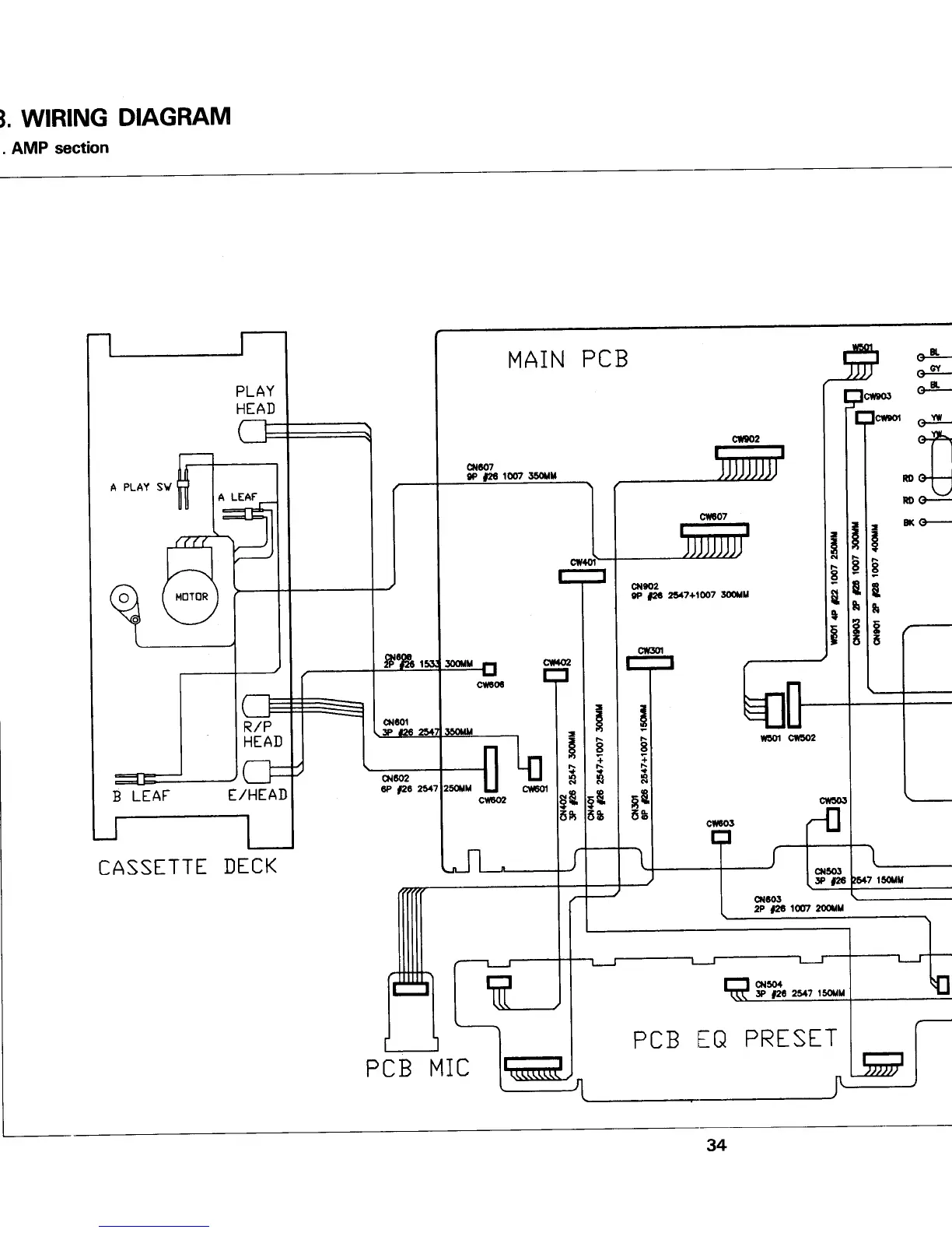
Detailed wiring diagram for the amplifier section, showing connections between PCBs and components.

Wiring Diagrams: CD Section

CD Section Wiring Diagram

Wiring diagram for the CD changer mechanism and related PCBs.

Circuit Diagrams: Amplifier Section

AMP Section Circuit Diagram

Detailed schematic of the amplifier circuit, including ICs and discrete components.

Circuit Diagrams: CD Section

CD Section Circuit Diagram

Schematic diagram for the CD player's electronic circuits.

Circuit Diagrams: Tuner Section

Tuner Section Circuit Diagram

Schematic diagram illustrating the tuner circuit's components and connections.

Exploded Views and Part Lists: Amplifier Section

Amplifier Section Part List Details

Exploded Views and Part Lists: CD Section

CD Section Part List Details

Mechanism Exploded Views and Part Lists: Cassette Section

Cassette Section Mechanism Details

Cassette Deck Mechanism Exploded View

Cassette Deck Mechanism Part List

CD Changer Section Exploded View

CD Changer Section Part List

Cassette Section Mechanism Parts (Continued)

Cassette Deck Mechanism Exploded Views and Part Lists

Cassette Deck Mechanism Part Lists

CD Changer Section Exploded View (Continued)

CD Changer Section Part List (Continued)

GM-521ZSW Part List - Mechanical Components

GM-521ZSW Part List - Mechanical Components (Final)

CD Changer Mechanism Part List

CD Changer Mechanism Part List (Continued)

CD Changer Mechanism Part List (Final)

Information for Repair

AMI-310 Defect Condition 1: R501 Defective

Repair method for AMI-310 when R501 is defective.

AMI-310 Defect Condition 2: Tray Open/Close Not Operational

Repair method for CD tray not operating on AMI-310.

AMI-310 Defect Condition 3: FM Tuner Bad Reception

Repair method for poor FM tuner reception on AMI-310.

AMI-960 Defect Condition 1: Lamp Not Lit

Repair method for AMI-960 when the lamp is not lit.

Information for Repair: CD and Tuner Issues

AMI-230 Defect Condition 1: Tray Open/Close or Bad Operation

Repair method for tray operation issues on AMI-230.

AMI-230 Defect Condition 2: TOC Cannot Read

Repair method for inability to read TOC on AMI-230 CD player.

Related product manuals