Do you have a question about the Daewoo KOG-36A5 and is the answer not in the manual?
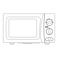
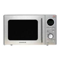
| Control Type | Touch |
|---|---|
| Turntable | Yes |
| Voltage | 230V |
| Frequency | 50Hz |
| Capacity | 36 litres |
| Features | Grill |
Guidelines for safe appliance operation, highlighting conditions that prohibit use.
Procedures for safe servicing, including emission checks and handling of leakage.
Guidance on placement, ventilation, and avoiding interference for installation.
Details on power source, voltage, current requirements, and cord safety.
Instructions to inspect the oven for damage before installation.
Guidance on setting microwave, grill, and combination cooking modes.
Recommendations for suitable utensils for microwave, grill, and combination cooking.
Describes circuit state when the door is closed and food is inside.
Explains circuit operation when the timer is set for cooking.
Details circuit behavior when the oven door is opened while cooking.
Ensuring the microwave oven is properly earthed before commencing repair work.
Caution regarding residual electric charge in the high voltage capacitor after power off.
Instructions for removing the outer cabinet of the microwave oven.
Steps for detaching and removing the microwave oven door assembly.
Procedure for taking apart the components of the microwave oven door.
Techniques to adjust the door seal for optimal contact with the oven front.
Steps to disassemble and remove components of the control panel.
Procedure for safely removing the high voltage capacitor.
Instructions for removing the magnetron assembly.
Steps to remove the fan motor and its associated assembly.
Procedure for removing the high voltage transformer.
Instructions for removing the insulator heater assembly.
Steps for disassembling and removing the heater components.
Description and adjustment of the primary interlock switch mechanism.
Details on secondary interlock and monitor switches, including adjustments.
Steps for replacing safety interlock switches and performing checks.
Procedure for testing the high voltage transformer continuity and resistance.
Steps to test the continuity and charge state of the high voltage capacitor.
Procedure for testing the continuity and resistance of the high voltage diode.
Steps to diagnose the magnetron for filament or short circuit issues.
Procedure for checking the continuity of the interlock monitor switch.
Testing continuity of primary and secondary interlock switches.
Procedure for checking the interlock monitor switch continuity.
Procedure for checking the primary interlock switch continuity.
Procedure for checking the secondary interlock switch continuity.
Exploded view and parts list for the door assembly.
Exploded view and parts list for the control panel assembly.
Exploded view and parts list for the main unit of the microwave.