12 Technical data
Installation manual
23
2MXM68+3(A)MXM+3(A)MXF+4MXM+5MXM
R32 Split series
3P600450-1G – 2021.03
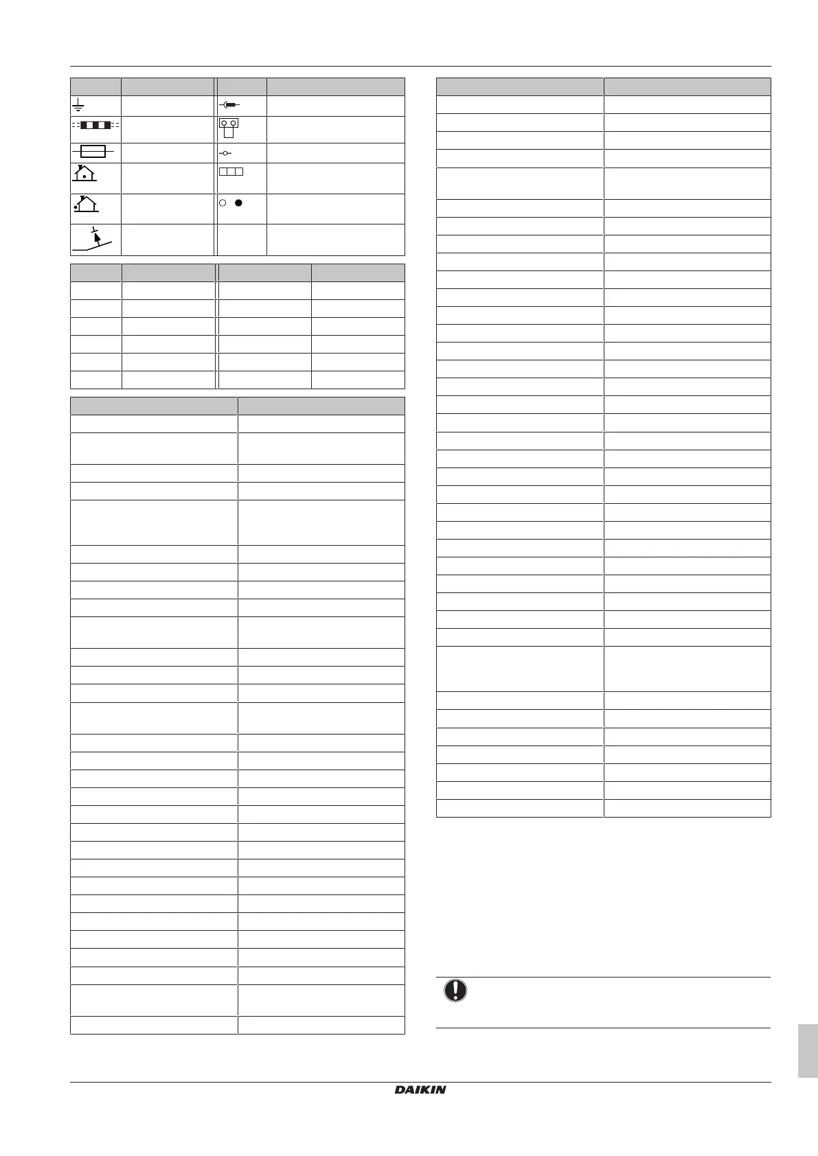
Symbol Meaning Symbol Meaning
Earth Relay connector
Field wiring Short-circuit connector
Fuse Terminal
Indoor unit Terminal strip
Outdoor unit Wire clamp
Residual current
device
Symbol Colour Symbol Colour
BLK Black ORG Orange
BLU Blue PNK Pink
BRN Brown PRP, PPL Purple
GRN Green RED Red
GRY Grey WHT White
YLW Yellow
Symbol Meaning
A*P Printed circuit board
BS* Pushbutton ON/OFF, operation
switch
BZ, H*O Buzzer
C* Capacitor
AC*, CN*, E*, HA*, HE*, HL*,
HN*, HR*, MR*_A, MR*_B, S*, U,
V, W, X*A, K*R_*, NE
Connection, connector
D*, V*D Diode
DB* Diode bridge
DS* DIP switch
E*H Heater
FU*, F*U, (for characteristics,
refer to PCB inside your unit)
Fuse
FG* Connector (frame ground)
H* Harness
H*P, LED*, V*L Pilot lamp, light emitting diode
HAP Light emitting diode (service
monitor green)
HIGH VOLTAGE High voltage
IES Intelligent eye sensor
IPM* Intelligent power module
K*R, KCR, KFR, KHuR, K*M Magnetic relay
L Live
L* Coil
L*R Reactor
M* Stepper motor
M*C Compressor motor
M*F Fan motor
M*P Drain pump motor
M*S Swing motor
MR*, MRCW*, MRM*, MRN* Magnetic relay
N Neutral
n=*, N=* Number of passes through ferrite
core
PAM Pulse-amplitude modulation
Symbol Meaning
PCB* Printed circuit board
PM* Power module
PS Switching power supply
PTC* PTC thermistor
Q* Insulated gate bipolar transistor
(IGBT)
Q*C Circuit breaker
Q*DI, KLM Earth leak circuit breaker
Q*L Overload protector
Q*M Thermo switch
Q*R Residual current device
R* Resistor
R*T Thermistor
RC Receiver
S*C Limit switch
S*L Float switch
S*NG Refrigerant leak detector
S*NPH Pressure sensor (high)
S*NPL Pressure sensor (low)
S*PH, HPS* Pressure switch (high)
S*PL Pressure switch (low)
S*T Thermostat
S*RH Humidity sensor
S*W, SW* Operation switch
SA*, F1S Surge arrester
SR*, WLU Signal receiver
SS* Selector switch
SHEET METAL Terminal strip fixed plate
T*R Transformer
TC, TRC Transmitter
V*, R*V Varistor
V*R Diode bridge, Insulated-gate
bipolar transistor (IGBT) power
module
WRC Wireless remote controller
X* Terminal
X*M Terminal strip (block)
Y*E Electronic expansion valve coil
Y*R, Y*S Reversing solenoid valve coil
Z*C Ferrite core
ZF, Z*F Noise filter
12.2 Piping diagram: Outdoor unit
Component PED category classification:
▪ High pressure switches: category IV
▪ Compressor: category II
▪ Accumulator: 4MXM80, 5MXM90 category II, other models
category I
▪ Other components: refer to PED article 4, paragraph 3
NOTICE
When the high pressure switch is activated, it MUST be
reset by a qualified person.

 Loading...