9 | Electrical installation
Installer reference guide
55
2MXM68+3(A)MXM+3(A)MXF+4MXM+5MXM
R32 Split series
4P600463-1C – 2020.08
Model A B
4MXM80 3- core cable 4.0 mm
2
H07RN-F (60245 IEC 66)
25A
5MXM90 32A
Electrical equipment must comply with EN/IEC 61000-3-12, the European/
International Technical Standard setting the limits for harmonic currents produced
by equipment connected to public low-voltage systems with input current >16 A
and ≤75 A per phase.
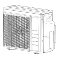
9.2 To connect the electrical wiring to the outdoor unit
1 Remove the switch box cover (1 screw).
2 Strip insulation (20mm) from the wires.
a Strip wire end to this point
b An excessive strip length may cause electrical shock or leakage
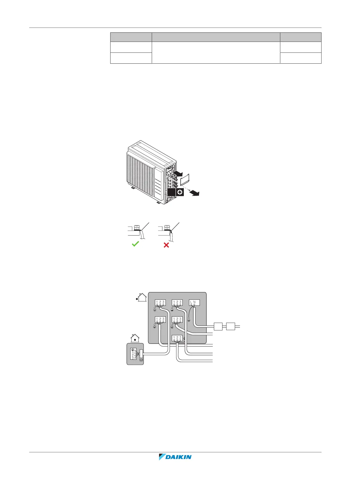
3 Connect the wires between the indoor and outdoor units so that the terminal
numbers match. Make sure to match the symbols for piping and wiring.
4 Make sure to connect correct wiring to correct room.
e-B
e-E
e-C
e-D
a-A
e-A
a-C a-D
a-E
a-B
b c
d
a Terminal for room (A, B, C, D, E)*
b Circuit breaker
c Earth leakage circuit breaker
d Power supply wire
e Interconnection wire for room (A, B, C, D, E)*
*May differ depending on the model.
5 Tighten the terminal screws securely using a Philips screwdriver.
6 Check that the wires do not disconnect by pulling them lightly.
7 Firmly secure the wire retainer to avoid external stress on wire terminations.
8 Pass the wiring through the cutout on the bottom of the protection plate.

 Loading...