8 Finishing the outdoor unit installation
Installation manual
19
2MXM68+3(A)MXM+3(A)MXF+4MXM+5MXM
R32 Split series
3P600450-1G – 2021.03
Model A B
3MXM40 3- core cable 2.5mm
2
H05RN-F (60245 IEC 57)
H07RN-F (60245 IEC 66)
3- core cable 4.0mm
2
H07RN-F (60245 IEC 66)
16A
2MXM68,
3AMXM52,
3AMXF52,
3MXF52,
3MXM52,
3MXF68,
3MXM68,
4MXM68
20A
4MXM80 3- core cable 4.0 mm
2
H07RN-F (60245 IEC 66)
25A
5MXM90 32A
Electrical equipment must comply with EN/IEC 61000-3-12, the
European/International Technical Standard setting the limits for
harmonic currents produced by equipment connected to public low-
voltage systems with input current >16 A and ≤75 A per phase.
7.2 To connect the electrical wiring to
the outdoor unit
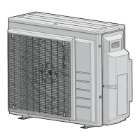
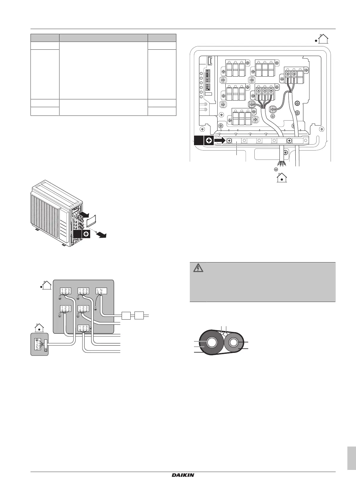
1 Remove the switch box cover (1 screw).
2 Connect the wires between the indoor and outdoor units so that
the terminal numbers match. Make sure to match the symbols
for piping and wiring.
3 Make sure to connect correct wiring to correct room.
e-B
e-E
e-C
e-D
a-A
e-A
a-C a-D
a-E
a-B
b c
d
a Terminal for room (A, B, C, D, E)*
b Circuit breaker
c Residual current device
d Power supply wire
e Interconnection wire for room (A, B, C, D, E)*
*May differ depending on the model.
4 Tighten the terminal screws securely using a Philips
screwdriver.
5 Check that the wires do not disconnect by pulling them lightly.
6 Firmly secure the wire retainer to avoid external stress on wire
terminations.
7 Pass the wiring through the cutout on the bottom of the
protection plate.
8 Make sure the electrical wiring does not contact with the gas
piping.
a Wire retainer
9 Reattach the switch box cover and the service cover.
8 Finishing the outdoor unit
installation
8.1 To finish the outdoor unit
installation
DANGER: RISK OF ELECTROCUTION
▪ Make sure that the system is earthed properly.
▪ Turn off the power supply before servicing.
▪ Install the switch box cover before turning on the power
supply.
1 Insulate and fix the refrigerant piping and cables as follows:
a Gas pipe
b Gas pipe insulation
c Interconnection cable
d Field wiring (if applicable)
e Liquid pipe
f Liquid pipe insulation
g Finishing tape
2 Install the service cover.
9 Configuration
9.1 About standby electricity saving
function
The standby electricity saving function:
▪ turns OFF the power supply to the outdoor unit and,
 Loading...