Outdoor Unit SiUS121827E
56 Part 3 Printed Circuit Board Connector Wiring Diagram
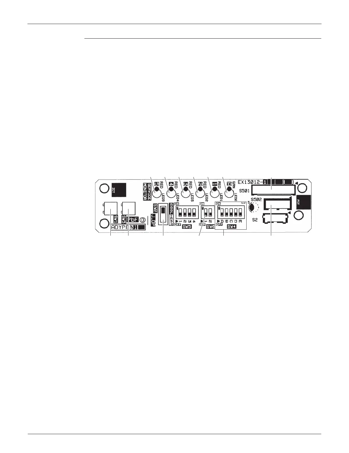
Service Monitor
PCB (PCB2)
SW6-2 and all the switches of SW5 have no function. Keep them OFF.
1) S501, S502 Connector for main PCB (PCB1)
2) LED A LED for service monitor (green)
3) LED1, LED2,
LED3, LED4,
LED5
LED for service monitor (red)
4) SW1 Forced cooling operation ON/OFF switch
∗ Refer to page 248 for details.
5) SW2 Operation mode switch
∗ Refer to page 248 for details.
6) SW3 Wiring error check switch
∗ Refer to page 249 for details.
7) SW4 Priority room setting switch
∗ Refer to page 274 for details.
8) SW6-1 NIGHT QUIET mode setting switch
∗ Refer to page 276 for details.
3P346711-10
S502SW6-1SW2SW3
LED5 LED4 LED3 LED2 LED1 LED A S501
SW1 SW4
 Loading...