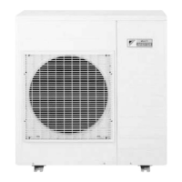
Si12-411A Outdoor Unit (80 / 90 Class)
Removal Procedure 231
6
The figure shows the
controller PCB.
S20: Electronic expansion valve
coil A port
S21: Electronic expansion valve
coil B port
S22: Electronic expansion valve
coil C port
S23: Electronic expansion valve
coil D port
S31: To CN14 (Pin 9)
S32: To CN11 (Pin 5)
S33: To S34 (Pin 10)
S40: Overload relay
S71: To S72 (Pin 8)
S80: Four way valve coil
S90: Thermistor (Outdoor air,
heat exchanger, and
discharge pipe)
S92: Gas pipe thermistor
S93: Liquid pipe thermistor
2. Removing the service
monitor PCB
1
Remove the service
monitor PCB by
releasing its tab.
3. Removing the inverter
PCB
1
Remove the 9 screws
of the inverter PCB.
Step
Procedure Points

 Loading...


