Installation manual
4
ER3~10DA
Air-cooled condensing units
4PW00410-1C
12 Remove the blind cap from the gas line stop valve (7) and the
liquid line stop valve (8).
13 Loosen the gland packing retainers of the gas line stop valve (7)
and the liquid line stop valve (8) using a hexagon wrench.
14 Partially open the gas line stop valve and the liquid line stop
valve and wait until the pressure indicated by the low pressure
gauge pointer equals the pressure indicated by the high
pressure gauge pointer.
15 Fully open the gas line stop valve and the liquid line stop valve.
16 Remove the R22 cylinder and the vacuum pump from the gauge
manifold.
17 Remove the hoses between the gauge manifold and the
condensing unit.
18 Check the stop valves for leakage.
Piping insulation
After finishing the leak test and vacuum drying, the piping must be
insulated to prevent reduction of the cooling capacity. Take into
account the following points when insulating the piping:
1. Provide a separate insulation for the gas line piping and the
liquid line piping.
2. Thoroughly insulate around the pipe connections.
3. Use Armaflex material with a thickness of 9 mm.
FIELD WIRING
Parts table
Power circuit and cable requirements
A power circuit (see table below) must be provided for connection of
the condensing unit. This circuit must be protected with the required
safety devices, i.e. a circuit breaker, a slow blow fuse on each phase
and an earth leak detector.
CENELEC system for cable designation
■ All field wiring and components must be installed by a
licensed electrician and must comply with relevant
European and national regulations.
■ The field wiring must be carried out in accordance
with the wiring diagrams (see figure 6, figure 7 and
figure 8) and the instructions given below.
■ Be sure to use a dedicated power circuit. Never use a
power supply shared by another appliance.
: Earth connection
L1, L2, L3 : Live line
N: Neutral
1: Power supply panel
2: Switch box condensing unit
F2,3,4U : Field fuses
S3S : Main isolator switch
: Earth leak detector
Model
Phase and
frequency
Voltage
Recommended
fuses
Cable type
(CENELEC Code)
ER3DAT1 3~50 Hz 220V 16 aM H07RN-F4G2.5
ER3DAV1 1~50 Hz 220-240V 25 aM H07RN-F3G4
ER3DAW1 3N~50 Hz 380-415V 10 aM H07RN-F5G2.5
ER5DAT1 3~50 Hz 220V 20 aM H07RN-F4G2.5
ER5DAW1 3N~50 Hz 380-415V 16 aM H07RN-F5G2.5
ER8DAT1 3~50 Hz 220V 32 aM H07RN-F4G6
ER8DAW1 3N~50 Hz 380-415V 25 aM H07RN-F5G4
ER10DAT1 3~50 Hz 220V 40 aM H07RN-F4G10
ER10DAW1 3N~50 Hz 380-415V 25 aM H07RN-F5G4
H Harmonised cable type
07 450/750 volts
V PVC wire insulation
RVulcanised natural rubber wire insulation
V PVC conductor insulation
N Neoprene conductor insulation
U Solid core
F Flexible core conductor
4 Number of conductors
G One conductor is the earth conductor (yellow/green)
X No earth conductor (yellow/green)
1.5
Cross-section of conductors (mm
2
)
Switch off the power circuit before making any connections
(switch off the circuit breaker, remove or switch off the
fuses).
Always use the cable indicated in the above table.
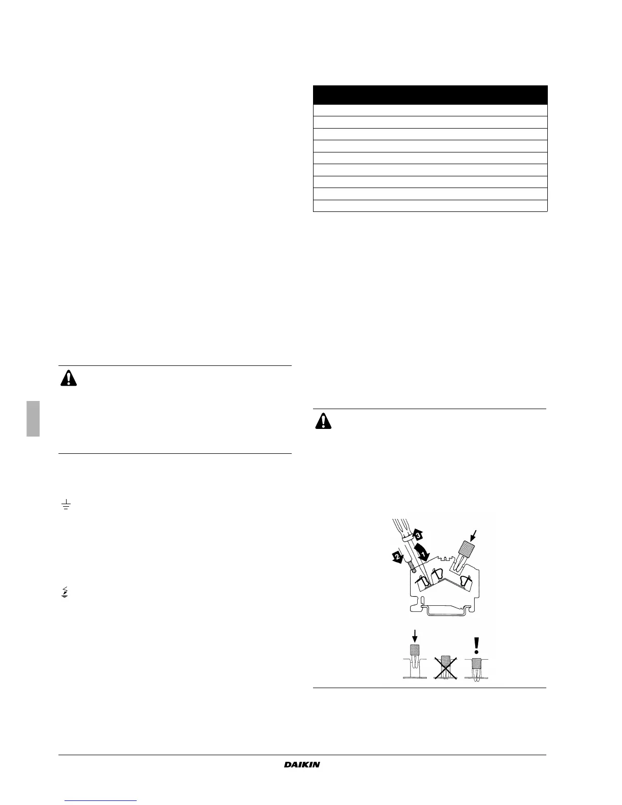
Remove maximum 8 mm of the PVC wire insulation when
connecting the wires to the terminals. To connect a wire,
depress the clamp spring using a screwdriver, insert the
wire and then remove the screwdriver (see figure). To
remove a wire, proceed in reverse order.
 Loading...