9 | Electrical installation
Installer reference guide
51
ARXM50-71+RXM42~71R2V1B + RXP50~71M2V1B + RXA42+50B2V1B +
RXF50+60B2V1B + RXF71A2V1B + RXJ50N2V1B + ARXF50~71A2V1B
R32 split series
4P513661-9J – 2020.05
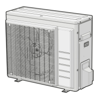
DANGER: RISK OF ELECTROCUTION
Disconnect the power supply for more than 10minutes, and measure the voltage at
the terminals of main circuit capacitors or electrical components before servicing.
The voltage MUST be less than 50VDC before you can touch electrical components.
For the location of the terminals, see the wiring diagram.
a Multimeter (DC voltage range)
b S80 – reversing solenoid valve lead wire
c S20 – electronic expansion valve lead wire
d S40 – thermal overload relay lead wire
e S90 – thermistor lead wire
f LED
g S70 – fan motor lead wire
9.1.2 Guidelines when connecting the electrical wiring
Keep the following in mind:
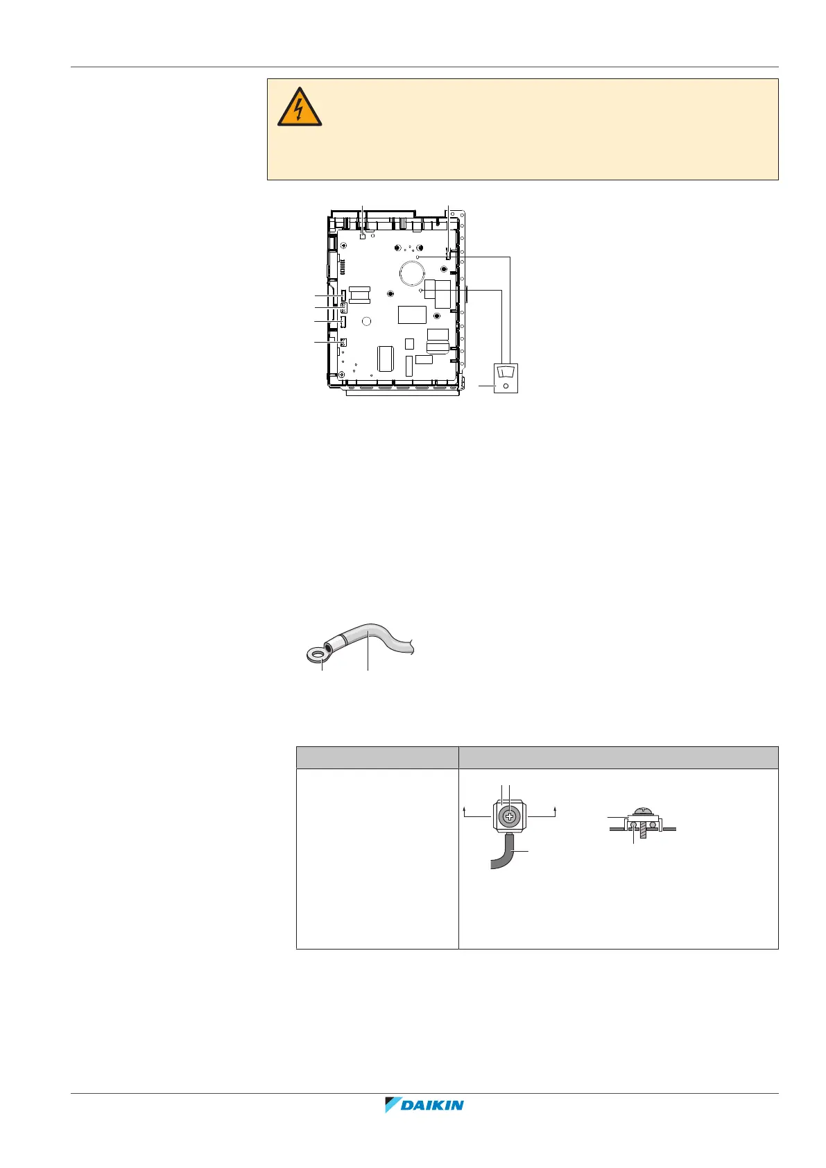
▪ If stranded conductor wires are used, install a round crimp-style terminal on the
end of the wire. Place the round crimp-style terminal on the wire up to the
covered part and fasten the terminal with the appropriate tool.
a Stranded conductor wire
b Round crimp-style terminal
▪ Use the following methods for installing wires:
Wire type Installation method
Single-core wire
a Curled single-core wire
b Screw
c Flat washer
 Loading...