Numeric Scoreboard
Maintenance and Troubleshooting
8-2
8.2 Lamp Replacement
Reference Drawing:
Digit Access .............................................................................................. Drawing A-27674
The primary service required for Daktronics baseball scoreboards is to periodically replace bad lamps.
Refer to the table in Section 3 to determine which wattage the scoreboard uses. Refer to Section 8.8 to
determine the part numbers. Do not use higher wattage lamps or damage to the circuit may result. Refer
to Drawing A-27674 to access a digit.
8.3 Lamp Drivers
Reference Drawings:
Layout, 16 Column Driver ....................................................................... Drawing A-123940
Layout, 8 Column Driver ......................................................................... Drawing A-123941
Important: When the lamp drivers are replaced, plugs P25 and P26 (if present) must be removed from
the old driver and plugged into the new driver.
In the scoreboard, the lamp drivers perform the task of switching digit lamps on and off (refer to
Drawings A-123940 and A-123941).
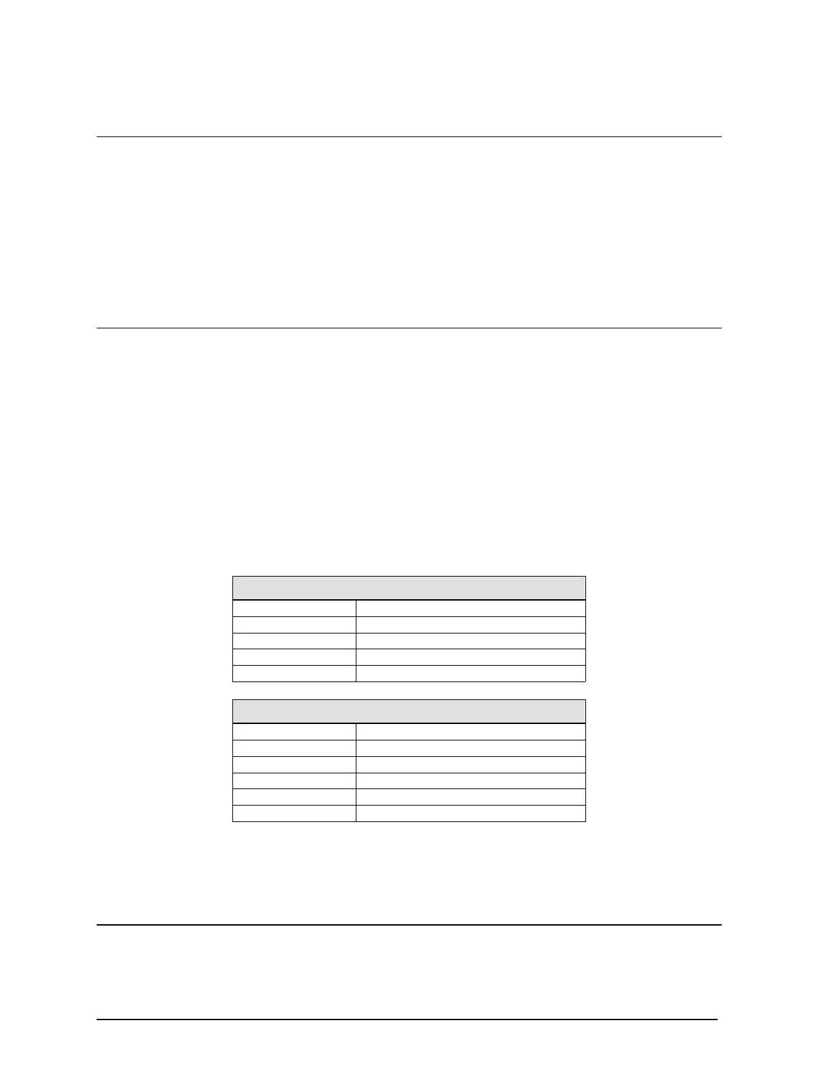
Each lamp driver has connectors providing power and signal inputs to the circuit, and outputs to the
digits and indicators. The connectors function as follows:
8-Column Lamp Driver
Connector No. Function
1 – 8 Outputs to digits and indicators
17 Control signal input
18 Power input for outputs 1 – 8
19 Power input (120V) for driver
16-Column Lamp Driver
Connector No. Function
1 – 16 Outputs to digits and indicators
17 Control signal input
18 Power input for outputs 1 – 8
19 Power input (120V) for driver
20 Power input for outputs 9 - 16
Output connectors to the digits and indicators each have nine pins. Pin 7 provides power (hot) to the
digit or indicators wired to that connector. The other eight pins provide switching connections.
8.4 Fuses
Reference Drawings:
Layout, 16 Column Driver .......................................................................Drawing A-123940
Layout, 8 Column Driver ......................................................................... Drawing A-123941
 Loading...

