GB
Danfoss Heating
5
3. Fix the wallplate and terminal block to the wall, or plaster box, as
required. Ensure that the screw heads do not protrude beyond
the vertical centre rib of the wallplate, or this will prevent the
module correctly locating onto the wallplate.
4. Surface cables can only enter from below the unit. Cut an
appropriate cable aperture in the wiring cover. If the wallplate is
mounted on a plaster box, cables can enter from the rear below
the terminal block.
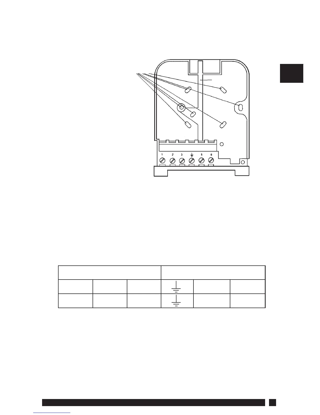
5. Electrical connections are simpli ed by using a Wiring Centre.
However, if this is not used, the wallplate terminal identi cation
is as shown.
If the system being controlled is 230 Vac, then terminals 3 and L
must be linked with insulated cable capable of carrying full load
current. Whilst the unit does not require an earth connection,
a terminal is provided on the wallplate for earth continuity
purposes.
6. Refer to the wiring diagrams on page 6-9, connect the unit as
shown.
Screw xing holes
(screwheads MUST NOT
protrude above centre rib)
Vertical
centre rib
Wallplate & Terminals
Load Mains Supply (via 3 amp fuse)
ON SPARE COM N L
123 5 6
 Loading...