5
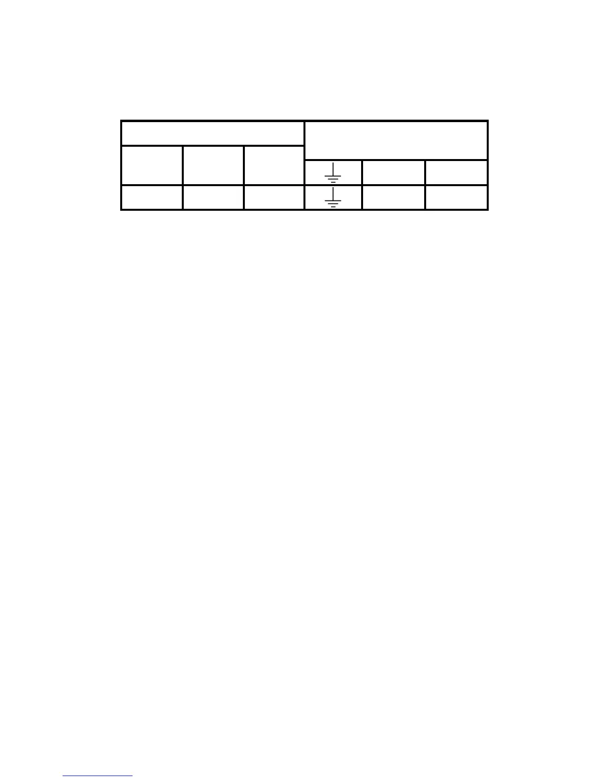
5. Electrical connections are simplifi ed by using a Wiring
Centre. However, if this is not used, the wallplate
terminal identifi cation is as shown.
If the system being controlled is 230 Vac, then
terminals 3 and L must be linked with insulated cable
capable of carrying full load current. Whilst the unit
does not require an earth connection, a terminal is
provided on the wallplate for earth continuity purposes.
6. Referring to the wiring diagrams on page 6-9, connect
the unit as shown.
7. Find out from the user whether the unit is required to
operate in 7-day mode (factory preset) or weekday/
weekend mode (5/2 day). To convert to 5/2 day
mode remove the small two-way connector from the
pins towards the left of the recess on the rear of the
module, then press the button marked R/S under the
fl ap to RESET the unit.
8. Ensure all dust and debris are cleared from the area.
Plug the module into the wallplate by locating it onto
the wallplate and, when fl ush with it, sliding it down,
ensure the hook at the top of the wallplate engages
with the slot at the back of the module.
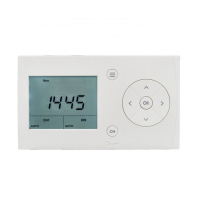
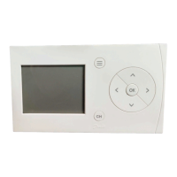
9. Before setting the programme, check the unit and
circuit. Press the SELECT button until the bar in the
display lines up with the word ON. Adjust the remote
thermostats to check the system operates correctly.
Installation
Load Mains Supply
(via 3 amp fuse)
ON SPARE COM
NL
123 5 6
 Loading...