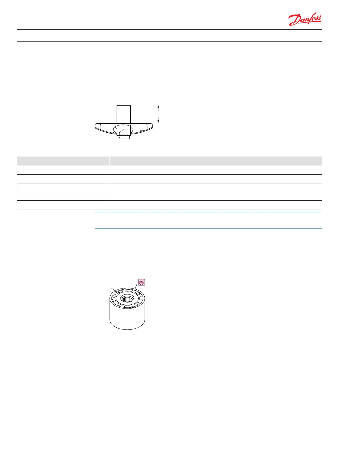
3. Inspect the spindle for wear.
4. Ensure the spindle is located correctly in the valve segment by measuring distance A. If this
dimension is not within the range shown in the table, it indicates that the spindle has moved in the
valve segment. Replace it.
Valve segment
Spindle location distance
Frame size Distance A mm [in]
060 27.5 ± .4 [1.08 ± 0.02]
080 32 ± .4 [1.25 ± 0.02]
110 34 ± .4 [1.34 ± 0.02]
160 38.9 ± .4 [1.49 ± 0.02]
250 44.2 ± .4 [1.74 ± 0.02]
Do not lap the valve segment to remove scratches. The hard treated surface is thin and lapping may
remove this surface. Removing the spindle loosens its tight press fit and allows it to move.
5. Inspect cylinder block assembly for wear or damage. If bearing is worn or damaged, replace the
complete block assembly. The bearing is not available as a separate part.
The piston bores must be smooth. The bearing plate surface must be free from scratches or nicks. The
holes for the bearing plate locating pins must be free from wear. The races for the synchronizing shaft
rollers must also be free from wear.
Cylinder block bearing
Repair Instructions
Series 51 and 51-1 Bent Axis Motors Repair Instructions
Inspection
18 11009449 • Rev BA • December 2014
 Loading...