6 Instructions RI8RE3ML © Danfoss 10/2016 AK-CC 210A
Setting:
1 Open parameter r12 and stop the regulation
2 Select electric connection based on the drawings on page 2
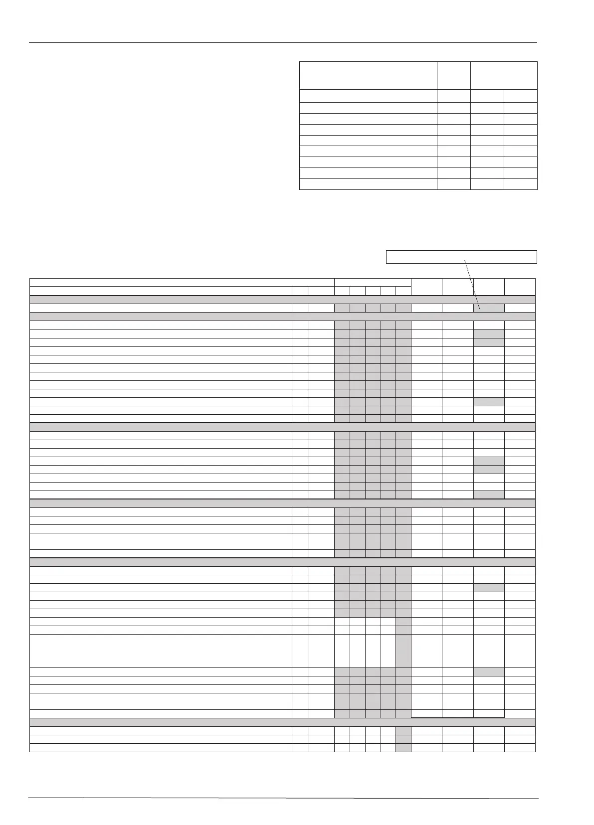
3 Open parameter o61 and set the electric connection number in it
4 Now select one of the preset settings from the table on the right-
hand side
5 Open parameter o62 and set the number for the array of preset-
tings
6 Open parameter r12 and start the regulation
7 Go through the survey of factory settings. Make any necessary
changes in the respective parameters.
8 For network. Set the address in o03 and then transmit it to the
gateway/system unit with setting o04.
Array 1-3: The settings in the grey fields will be changed
English
Parameters Variant of AK-CC
Min.-
value
Max.-
value
Factory
setting
Actual
setting
Function Codes 1 2 3 4 5
Normal operation
Temperature (set point) --- -50.0°C 50.0°C 2.0°C
Thermostat
Differential *** r01 0.0 K 20.0K 2.0 K
Max. limitation of setpoint setting *** r02 -49.0°C 50°C 50.0°C
Min. limitation of setpoint setting *** r03 -50.0°C 49.0°C -50.0°C
Adjustment of temperature indication r04 -20.0 K 20.0 K 0.0 K
Temperature unit (°C/°F) r05 °C °F °C
Correction of the signal from S4 r09 -10.0 K +10.0 K 0.0 K
Correction of the signal from S3 r10 -10.0 K +10.0 K 0.0 K
Manual service, stop regulation, start regulation (-1, 0, 1) r12 -1 1 0
Displacement of reference during night operation r13 -20.0 K 20.0 K 0.0 K
Definition and weighting, if applicable, of thermostat sensors - S4% (100%=S4, 0%=S3) r15 0% 100% 100%
Activation of reference displacement r40 r39 OFF ON OFF
Value of reference displacement (activate via r39 or DI) r40 -50.0 K 50.0 K 0.0 K
Alarm
Delay for temperature alarm A03 0 min 240 min 30 min
Delay for door alarm *** A04 0 min 240 min 60 min
Delay for temperature alarm after defrost A12 0 min 240 min 90 min
High alarm limit *** A13 -50.0°C 50.0°C 8.0°C
Low alarm limit *** A14 -50.0°C 50.0°C -30.0°C
Alarm delay DI1 A27 0 min 240 min 30 min
Alarm delay DI2 A28 0 min 240 min 30 min
Signal for alarm thermostat. S4% (100%=S4, 0%=S3) A36 0% 100% 100%
Compressor
Min. ON-time c01 0 min 30 min 0 min
Min. OFF-time c02 0 min 30 min 0 min
Time delay for cutin of comp.2 c05 0 sec 900 sec 5 sec
Compressor relay 1 must cutin and out inversely
(NC-function)
c30 0
OFF
1
ON
0
OFF
Time delay for cutin of compressor 2 during defrost c92 0 s 30 s 5 s
Defrost
Defrost method (none/EL/GAS) d01 no GAS GAS
Defrost stop temperature d02 0.0°C 25.0°C 6.0°C
Interval between defrost starts d03 0 hours
240 hours
8 hours
Max. defrost duration d04 0 min 360 min 45 min
Displacement of time on cutin of defrost at start-up d05 0 min 240 min 0 min
Drip off time d06 0 min 60 min 0 min
Delay for fan start after defrost d07 0 min 60 min 0 min
Fan start temperature d08 -50.0°C 0.0°C -5.0°C
Fan cutin during defrost
0: Stopped
1: Running
2: Running during pump down and defrost
d09 0 2 1
Defrost sensor (0=time, 1=S5, 2=S4) d10 0 2 0
Pump down delay d16 0 min 60 min 0 min
Max. aggregate refrigeration time between two defrosts d18 0 hours 48 hours 0 hours
Defrost on demand - S5 temperature’s permitted variation during frost build-up. On
central plant choose 20 K (=off)
d19 0.0 K 20.0 k 20.0 K
Max. duration of -d- in display d40 5 min 240 min 30 min
Fan
Fan stop at cutout compressor F01 no yes no
Delay of fan stop F02 0 min 30 min 0 min
Fan stop temperature (S5) F04 -50.0°C 50.0°C 50.0°C
Auxiliary table for settings
(quick-setup)
Defrost
stop on
time
Defrost stop
on S5
Preset settings (o62) 1 2 3
Temperature (SP) 4°C 2°C -24°C
Max. temp. setting (r02) 6°C 4°C -22°C
Min. temp. setting (r03) 2°C 0°C -26°C
Alarm limit high (A13) 10°C 8°C -15°C
Alarm limit low (A14) -5°C -5°C -30°C
Interval between defrost (d03) 6 h 6h 12h
Defrost sensor: 0=time,1=S5, 2=S4 (d10) 0 1 1
DI1 configuration (o02) 10 10 10
 Loading...