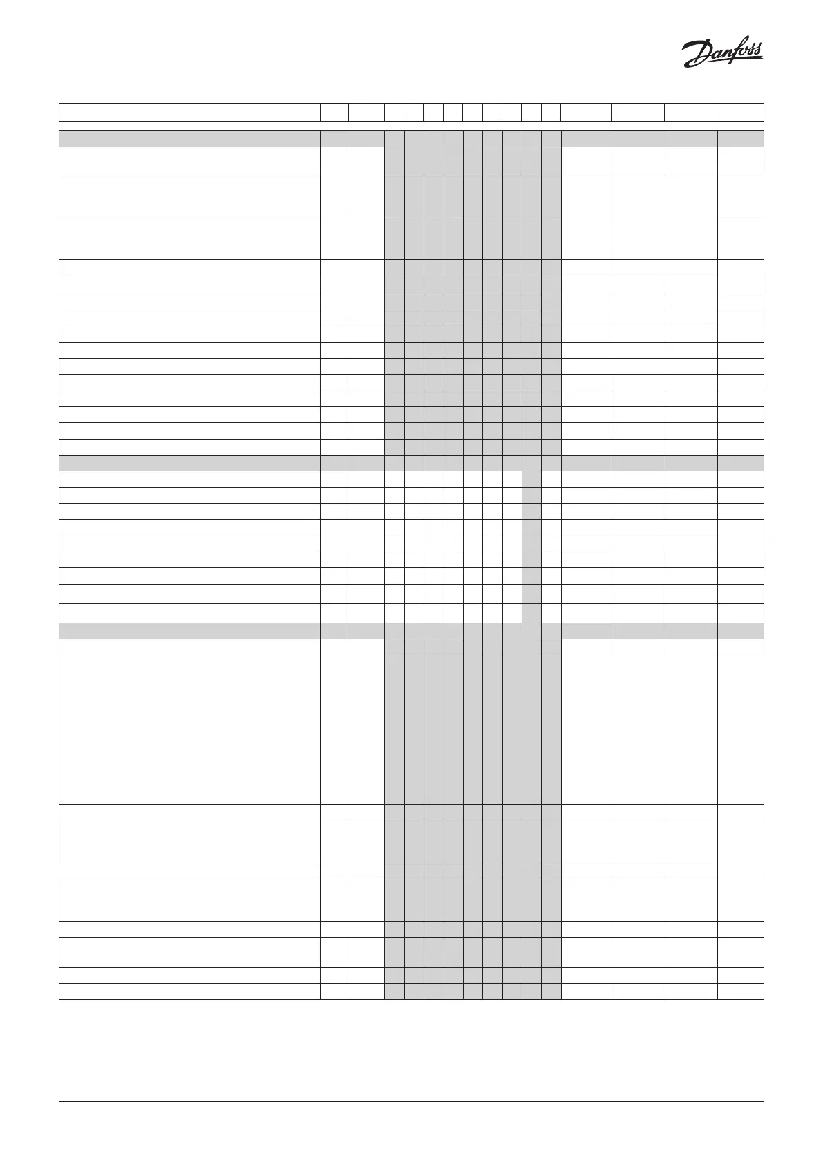
Single Coil - continued R-W Code 1 2 3 4 5 6 7 8 9 Min. Max. Fac. Actual
Real time clock
Defrost start via defrost schedule: 0/off=no.
1/on=yes
1-2 t00 1 1 1 1 1 1 1 1 1 0/off 1/on 0/off
Six start times for defrost.
Setting of hours.
0=OFF
1-2 t01 -
t06
1 1 1 1 1 1 1 1 1 0 hrs 23 hrs 0
Six start times for defrost.
Setting of minutes.
0=OFF
1-2 t11 -
t16
1 1 1 1 1 1 1 1 1 0 min. 59 min. 0
Clock - Setting of hours
0-1 t07 1 1 1 1 1 1 1 1 1 0 hrs 23 hrs 0
Clock - Setting of minutes
0-1 t08 1 1 1 1 1 1 1 1 1 0 min. 59 min. 0
Clock - Setting of date
0-1 t45 1 1 1 1 1 1 1 1 1 1 day 31 days 1
Clock - Setting of month
0-1 t46 1 1 1 1 1 1 1 1 1 1 mon. 12 mon. 1
Clock - Setting of year
0-1 t47 1 1 1 1 1 1 1 1 1 0 years 99 years 0
Defrost schedule for Mondays is active at On/1 1-2 t51 1 1 1 1 1 1 1 1 1 0/Off 1/On 1/On
Defrost schedule for Tuesdays is active at On/1 1-2 t52 1 1 1 1 1 1 1 1 1 0/Off 1/On 1/On
Defrost schedule for Wednesdays is active at On/1 1-2 t53 1 1 1 1 1 1 1 1 1 0/Off 1/On 1/On
Defrost schedule for Thursdays is active at On/1 1-2 t54 1 1 1 1 1 1 1 1 1 0/Off 1/On 1/On
Defrost schedule for Fridays is active at On/1 1-2 t55 1 1 1 1 1 1 1 1 1 0/Off 1/On 1/On
Defrost schedule for Saturdays is active at On/1 1-2 t56 1 1 1 1 1 1 1 1 1 0/Off 1/On 1/On
Defrost schedule for Sundays is active at On/1 1-2 t57 1 1 1 1 1 1 1 1 1 0/Off 1/On 1/On
Humidity
Setpoint for cut-in of humidity function 0-2 h23 1 0 % 100 % 70
Difference for humidity function 1-2 h24 1 1 % 30 % 5
Alarm limit for high humidity (too damp) 1-2 h25 1 0 % 100 % 100
Alarm limit for low humidity (too dry) 1-2 h26 1 0 % 100 % 0
Delay time for a humidity alarm 1-2 h27 1 0 min. 240 min. 60
Humidity function during defrosting 1-2 h28 1 0/Off 1/On 0/Off
Setpoint for RH% at input signal on 0 V 1-2* h29 1 0 % "h30" 0
Setpoint for RH% at input signal on 10 V 1-2* h30 1 "h29" 100 % 100
Use humidity control 1-2* h31 1 0/Off 1/On 0/Off
Miscellaneous
Delay of output signals after power failure 1-2 o01 1 1 1 1 1 1 1 1 1 0 sec 600 sec 5
Input signal on DI1. Function:
0=not used. 1=status on DI1. 2=door function with
alarm when open. 3=door alarm when open. 4=defrost
start (pulse-signal). 5=ext.main switch. 6=night
operation 7=thermostat band changeover (activate
r21). 8=alarm function when closed. 9=alarm function
when open. 10=Appliance cleaning (pulse signal).
11=forced cooling at hot gas defrost, 12=Open night
cover. 14=Refrigeration stopped (forced closing).
15=case shutdown. 16=light. 20=Refrigerant alarm.
21= adaptive liquid control when short-circuited.
1-2* o02 1 1 1 1 1 1 1 1 1 0 21 0
Network address 1-3* o03 1 1 1 1 1 1 1 1 1 0 240 0
On/Off switch (Service Pin message)
IMPORTANT! o61 must be set prior to o04
(used at Lon 485)
1-2 o04 1 1 1 1 1 1 1 1 1 0/Off 1/On 0/Off
Access code 3 (all settings) 3-3 o05 1 1 1 1 1 1 1 1 1 0 999 0
Used sensor type: 0=Pt1000, 1=PTC1000, 2=Ntc5K,
3=Ntc10K. (S2 and S6 are not affected. They are always
Pt1000 ohms)
1-3* o06 1 1 1 1 1 1 1 1 1 0/Pt 3/N10 0/Pt
Max. hold time after coordinated defrost 1-2 o16 1 1 1 1 1 1 1 1 1 0 min. 360 min. 20
Select signal for display view. S4%
(100%=S4, 0%=S3)
1-2 o17 1 1 1 1 1 1 1 1 1 0 % 100 % 100
Pressure transmitter working range – min. value 1-3* o20 1 1 1 1 1 1 1 1 1 -1 bar 5 bar -1
Pressure transmitter working range – max. value 1-3* o21 1 1 1 1 1 1 1 1 1 6 bar 200 bar 12
© Danfoss | DCS (vt) | 2019.07
12 | AN294432763974en-000201

 Loading...


