Connections
Overview of outputs and applications
40
41
42
5V
s
AI1
43
44
AI2
45
46
AI3
47
48
AI4
49
50
AI5
51
52
AI6
53
54
DI1*
60
61
DI2
70
71
AO1
PWM
83
84
85
B
A
MODBUS
115 - 230V AC
L
N
1
2
3
8
9
7
10
11
12
DO2
13
14
DO3
15
16
17
DO4
18
19
20
DO5
21
22
DO6
115-230V AC
30
31
DI3
Danfoss
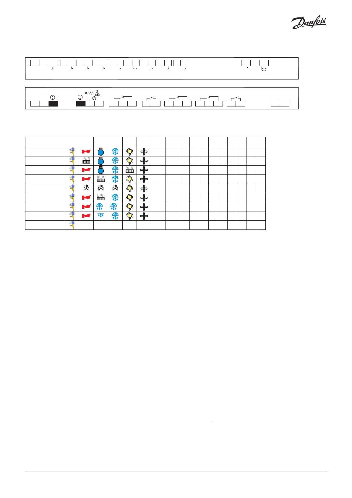
See also wiring diagrams earlier in the instruction.
) Custom set-up of relays
Application DO1 DO2 DO3 DO4 DO5 DO6 AO1 AI1 AI2 AI3 AI4 AI5 AI6
AI7/
DI1
DI2 DI3
1
•
Pe S2 S3 S4 S5 S6
• • •
2
•
Pe S2 S3 S4 S5 S6
• • •
3
•
Pe S2 S3 S4 S5 S6
• • •
4
•
Pe S2 S3 S4 S5 S6
• • •
5
suction
drain
hotgas
•
Pe S2 S3 S4 S5 S6
• • •
6
•
Pe S2 S3 S4 S5 S3B
• • •
7
B A
•
Pe S2 S3 S4 S5 S3B S5B
• •
8
humidity
•
Pe S2 S3 S4 S5 S6 RH%
• •
9
•
)
•
)
•
)
•
)
•
)
•
Pe S2 S3 S4 S5 S6
• • •
AI1
Pressure transmitter
AKS 32R
Connect to terminal 40, 41 and 42.
(Use cable 060G1034: Black=40, Brown=41, Blue=42)
The signal from one pressure transmitter can be received by up to
10 controllers. But only if there are no significant pressure drops
between the evaporators to be controlled. See drawing on page 5.
Please note: when replacing AK-CC550 with AK-CC55, S and
ground must be switched.
AI2 - AI7
Primarily for temperature inputs
S2
Pt 1000 ohm sensor AKS11
S3, S4, S5
Pt 1000 AKS11, PTC 1000 EKS111, NTC5K EKS211 or NTC10K
EKS221 sensor. All have to be of the same type.
S3, return air sensor, placed in the warm air before the evaporator
S4, discharge air sensor, placed in the cold air after the evaporator
(the need for either S3 or S4 can be selected in the
configuration)
S5, defrost sensor, placed on the evaporator
S6, Pt 1000 ohm sensor
(If the Di1 input is used for a temperature measurement, it will
appear as AI7.)
DI1
Digital input signal.
The defined function is active when the input is short-circuited or
opened, depending on the function defined in o02.
DI2
Digital input signal.
The defined function is active when the input is short-circuited or
opened, depending on the function defined in o37.
AO1
Analogue output signal
Analogue 0-10 V (currently not used)
Pulse width modulated signal
Can be used for fast control of rail heat via an external power
solid state relay.
MODBUS
For data communication.
Terminal 83 = B-
Terminal 84 = A+
Terminal 85 = screen
It is important that the installation of the data communication
cable is performed correctly.
See separate literature no. RC8AC902
© Danfoss | DCS (vt) | 2019.07
6 | AN294432763974en-000201

 Loading...


