Setting of presettings (r89). After
setting 1-5,
setting is returned to 0.
Food type =
1
Vege-
tables
2
Milk
3
Meat/
fish
4
Frost
5
Ice
Temperature (r00) 8 °C 0 °C -2 °C -20 °C -24 °C
Max. temp. setting (r02) 10 °C 4 °C 2 °C -16 °C -20 °C
Min. temp. setting (r03) 4 °C -4 °C -6 °C -24 °C -28 °C
Upper alarm limit (A13) 14 °C 8 °C 8 °C -15 °C -15 °C
Lower alarm limit (A14) 0 °C -5 °C -5 °C -30 °C -30 °C
Upper alarm limit for S6 (A22) 14 °C 8 °C 8 °C -15 °C -15 °C
Lower alarm limit for S6 (A23) 0 °C -5 °C -5 °C -30 °C -30 °C
Can only be set when r12=0.
Food type
Get a good start
With the following procedure you can start regulation very quickly:
1. Open parameter r12 and stop the regulation (in a new and
not previously set unit, r12 will already be set to 0 which
means stopped regulation.)
2. Select application based on the wiring diagrams on pages 2-4
3. Open parameter o61 and set the application number
4. For network. Set the address in o03
5. Then select a set of presets from the "Food type" help table
6. Open parameter r89 and set the number for the array of
presettings. The few selected settings will now be transferred
to the menu.
7. Set the desired cut-out temperature r00
8. Select refrigerant via parameter o30
9. Set the pressure transmitter min. and max. range
10. Set the desired defrost method in d01
11. Set the interval time between defrost starts in d03
12. Set the desired defrost sensor in d10
13. Set the maximum defrost time in d04
14. Set the defrost stop temperature in d02
15. Open parameter r12 and start the regulation
16. Go through the survey of factory settings. The values in the
grey cells are changed according to your choice of settings.
Make any necessary changes in the respective parameters.
17 • Send address to system unit:
• MODBUS: Activate scan function in system unit
• If another data communication card is used in the controller:
- Lon RS485: Activate the function o04
- Ethernet: Use the MAC address
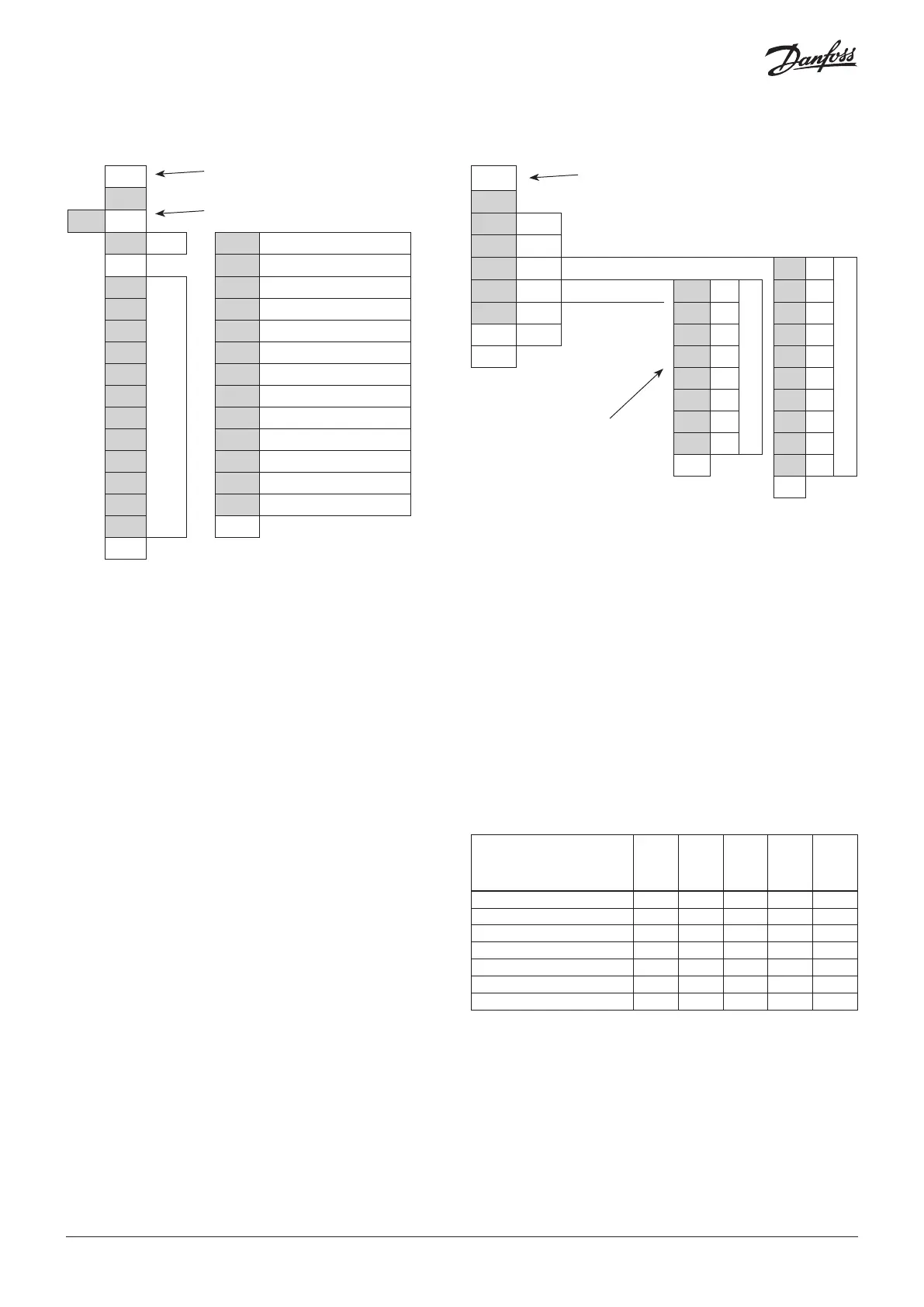
SET
Set
(PS)
<
cFg SET
Þ
r12 Main switch
<
o61 Application
r-- o03 MODBUS address
A--
Menu groups
See also the following pages.
r89 Food type
c-- r00 Cut-out temperature
d-- o30 Refrigerant type
n-- o20 Min. transmitter range
F-- o21 Max. transmitter range
t-- d01 Defrost method
h-- d03 Defrost interval
o-- d10 Defrost sensor
p-- d04 Max. defrost time
q-- d02 Defrost stop temperature
u-- <
< (Return)
(Return)
Parameter grouping at display operation
SET button, 3 s: Configuration settings
PS: Password (if any)
Info button, 3 s: Information for service
use
<
Inf
StA SET See status message. See operating status page 18.
App SET See selected application
in SET
Þ
AI1
PE
Read input status
out SET
Þ
do1
Akv
Read output status
AI2
S2
buS SET MODBUS quality do2
*
AI3
S3
SoF SET See SW version do3
*
AI4
S4
< do4
*
AI5
S5
(Return)
do5
*
AI6
**
do6
*
di1
**
do7
*
di2
**
Ao1
*
di3
**
<
Ao1
**
(Return)
<
(Return)
Output status
When you want info on a relay
output, the dot will show
whether the relay is activated
(energized) for, e.g.:
do4 = not activated
do.4 = activated
*)
The output's function.
(Determined at configuration).
Forced control of a function can be
performed in codes q11 to q27.
**)
The input's function.
(Determined at configuration).
© Danfoss | DCS (vt) | 2019.07
AN294432763974en-000201 | 9

 Loading...


