3.7 DHP-AL, DHP-AL Opti
The brine pipes can be connected on either the left or right-hand sides of the heat pump.
3
5
6
2
11
15
14
10
12
13
17
7
16
4
89
1
1538 (±10)
455
596
690
40±10
455
690
40±10
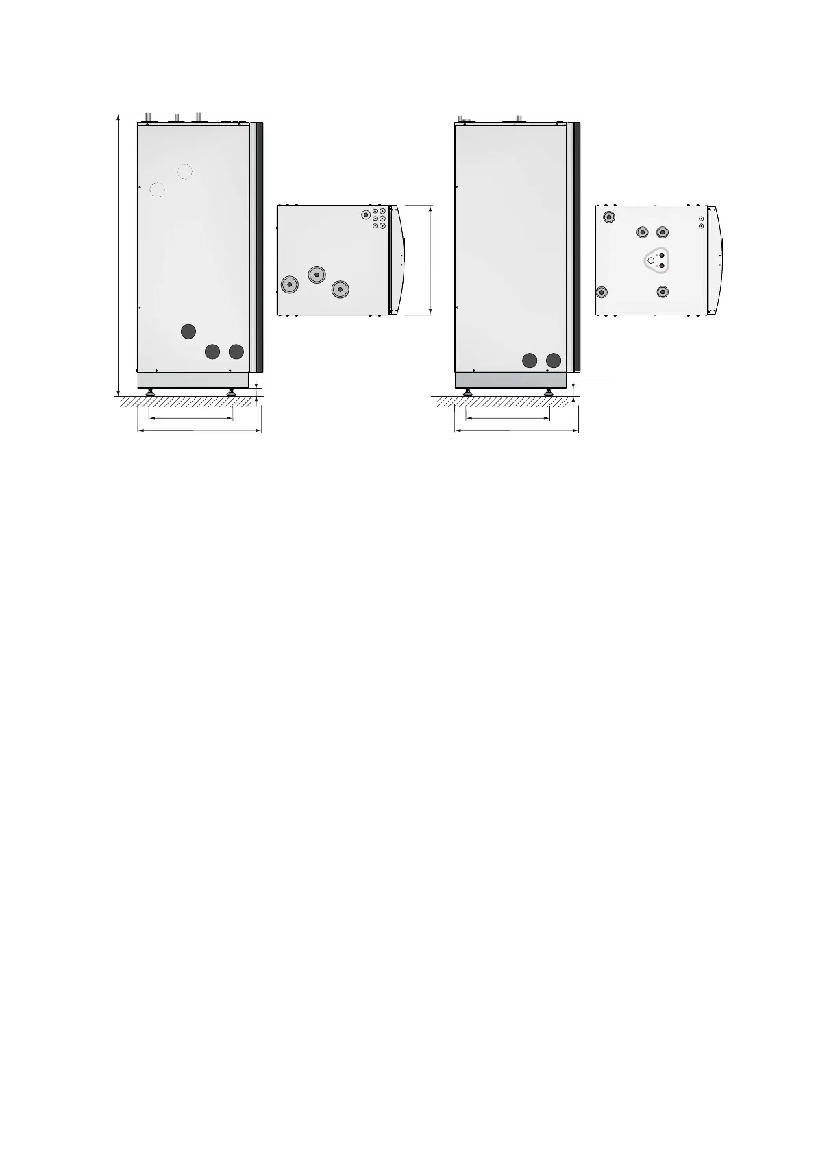
Figure 6. Dimensions and connections heat pump and water heater
Symbol explanation
Heat pump
1 Brine in, 28 Cu 5 Heating system supply pipe, 22 Cu: 6-10 kW, 28 Cu: 12
kW
2 Brine out, during normal operation, 28 Cu 6 Heating system return pipe, 22 Cu: 6-10 kW, 28 Cu: 12 kW
3 Brine out during defrosting to hwh pos 8, 28 Cu 7 Lead-in power and sensor lead
4 Return line from water heater pos 9, 28 Cu
Symbol explanation
Water heater
8 Connection for brine out when defrosting from
pos 3
13 Cold water line, 22 mm
9 Water heater, return pipe to pos 4 14 Supply to water heater coil
10 Bleed valve, at stainless steel water heater 15 Brine, expansion outlet when outdoor unit is positioned at
high level
11 Brine out during defrosting, 28 Cu 16 Lead-in sensor lead
12 Hot water line, 22 mm 17 Safety valve for temperature and pressure (only applies to
certain models)
Installation instructions VMBMA1002 – 13
 Loading...