Danfoss – 19VUBMA102
3.1 Display
The display of the control computer shows information about the heat pump’s operation, sta-
tus and any alarms, in text form. The status, indicated by symbols, is also shown in the lower
section which shows the heat pump’s active process.
Operating modes
Appear with applicable heat pump operating status text.
Operating mode Meaning
(OFF)
The installation is fully switched off.
Remember that if the operating mode OFF is to be used for
long periods during the winter, the water in the heating sys-
tem in the installation must be drained, otherwise there is a
risk of frost damage.
⚠
AUTO The heat pump and the auxiliary heater are automatically controlled
by the control computer.
HEATPUMP The control computer is controlled so that only the heat pump unit
(compressor) is allowed to operate.
ADD. HEAT The control computer only permits the auxiliary heater to be in opera-
tion. This operating mode can be used when a new installation is
being used, when the brine system is not ready for operation.
HOT WATER In this mode the heat pump only produces hot water, no heat goes to
the heating system.
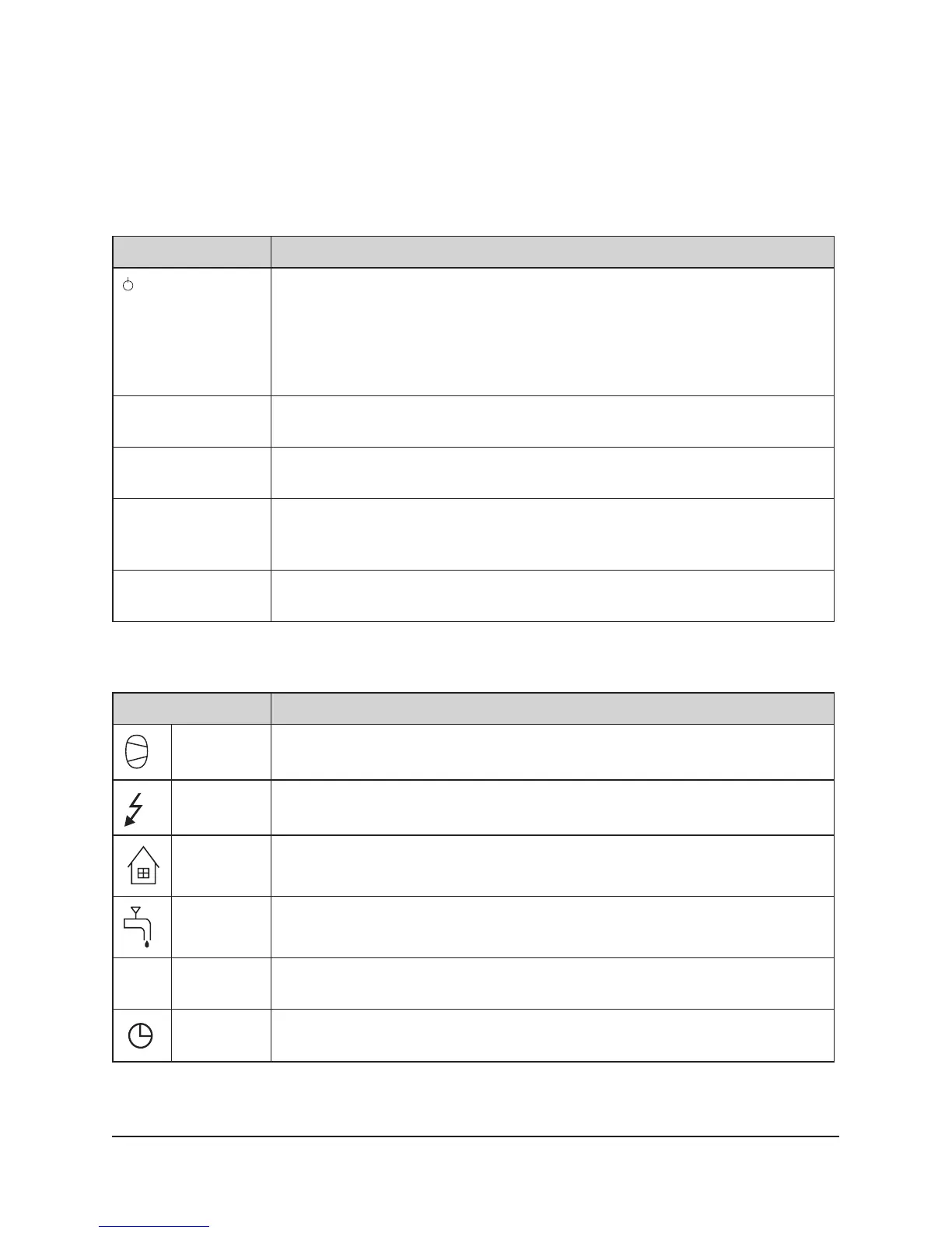
Symbols
Displays the operating status of the heat pump using symbols.
Symbol Meaning
HP Indicates that the compressor is in operation. An “F” next to the sym-
bol indicates that a flow switch is installed.
Indicates that the auxiliary heater is in operation. Number of auxiliary
power stages indicated by digit.
HOUSE Indicates that the 3-way valve position is for heat production for the
house.
TAP Indicates that the 3-way valve’s position is for hot water production.
VL SYSTEM Indicates the set system VL / D / VL+F / D+F (+F indicates that a flow
switch is installed)
CLOCK Indicates that tariff control is active.
 Loading...