Installation Guide DLX seriesL00410622-01 23
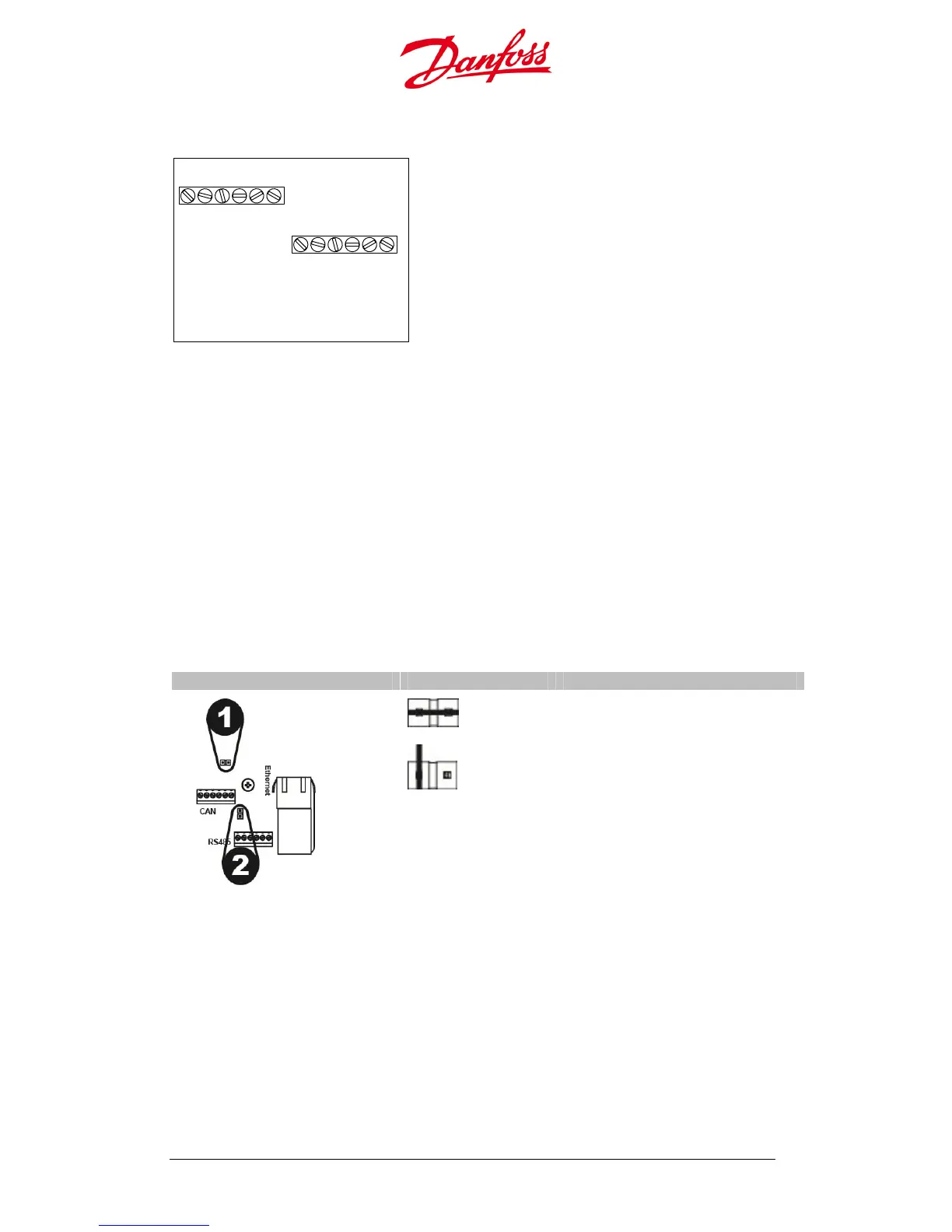
CAN and RS-485 connection pinout
2.4.5.2. Jumper Position for Termination Resistance
With multiple inverters connected the jumper located behind the CAN / RS-485 terminal
activates the termination resistance when the pins are terminated (short-circuited). This
minimizes signal reflections in the cables and helps to avoids interference.
• Single inverter: The two pins must be terminated (Default).
• Several inverters connected: The master-follower configuration requires terminated
pins on the first inverter and on the last inverter in the linked series. The pins must be
disconnected on the inverters between the first and last inverters in the linked series.
• To disconnect the pins, the jumper must be pulled up and placed only on one of the
pins.
• Be careful not to bend the pins when removing or installing the jumper!
Table 2.4.3: Jumper for multiple inverters in linked series
Network connection
umper Position Pins
1. CAN termination resistance
2. RS-485 termination resistance
The pins are terminated.
The pins are disconnected.
2.5. Required Safety Equipment
Safety equipment includes switches or circuit breakers to disconnect power sources,
fuses or circuit breakers to protect conductors from overheating and surge protection
to protect the equipment from voltage bursts and surges.
L
H
COMGND
L
H
COMGND
CAN
A(-)
B(+)
GND
A(-)
B(+)
GND
RS-485
 Loading...