Installation Guide DLX seriesL00410622-01 35
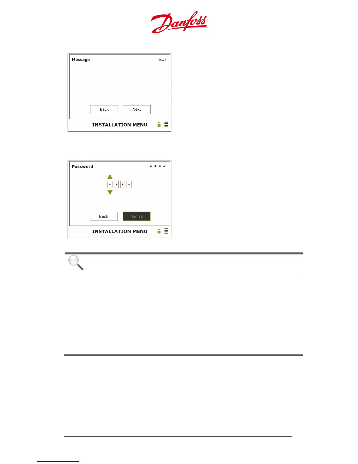
16. Message
Enter – Call up the keyboard
This message field is to help distinguish and
identify specific inverters in a larger PV plant, or
for any other information.
Left – Back
Right – Next
Enter – Confirm
17. Owner Password
Enter – Call up the digits
Default: 0003.
Change the password to 4 optional digits
Left – Back
Right – Finish
Enter – Confirm
NOTICE
With several inverters connected it must be checked that the installation is carried
out on all the follower inverters.
• Look at the displayed menu and the LEDs: It is not carried out correctly if the
installation menu is still displayed and/or the green LED is not lit and the
yellow and red LEDs are lit.
• Check that the connection of the CAN cables are correct, that the AC and DC
switches are ON and that the voltage are >184 V
AC
, and >230 V
DC
and there is
greater than 7 W
DC
of power
• If the Start Up phase is correctly carried out the inverters are ready to use. They
are fully automatic during normal operation, and no manual control is
necessary for feeding power into the grid.
A warning box is displayed if an error occurred during installation:
 Loading...