4.0 Modbus network denitions
4.1 Multipoint serial bus infrastructure
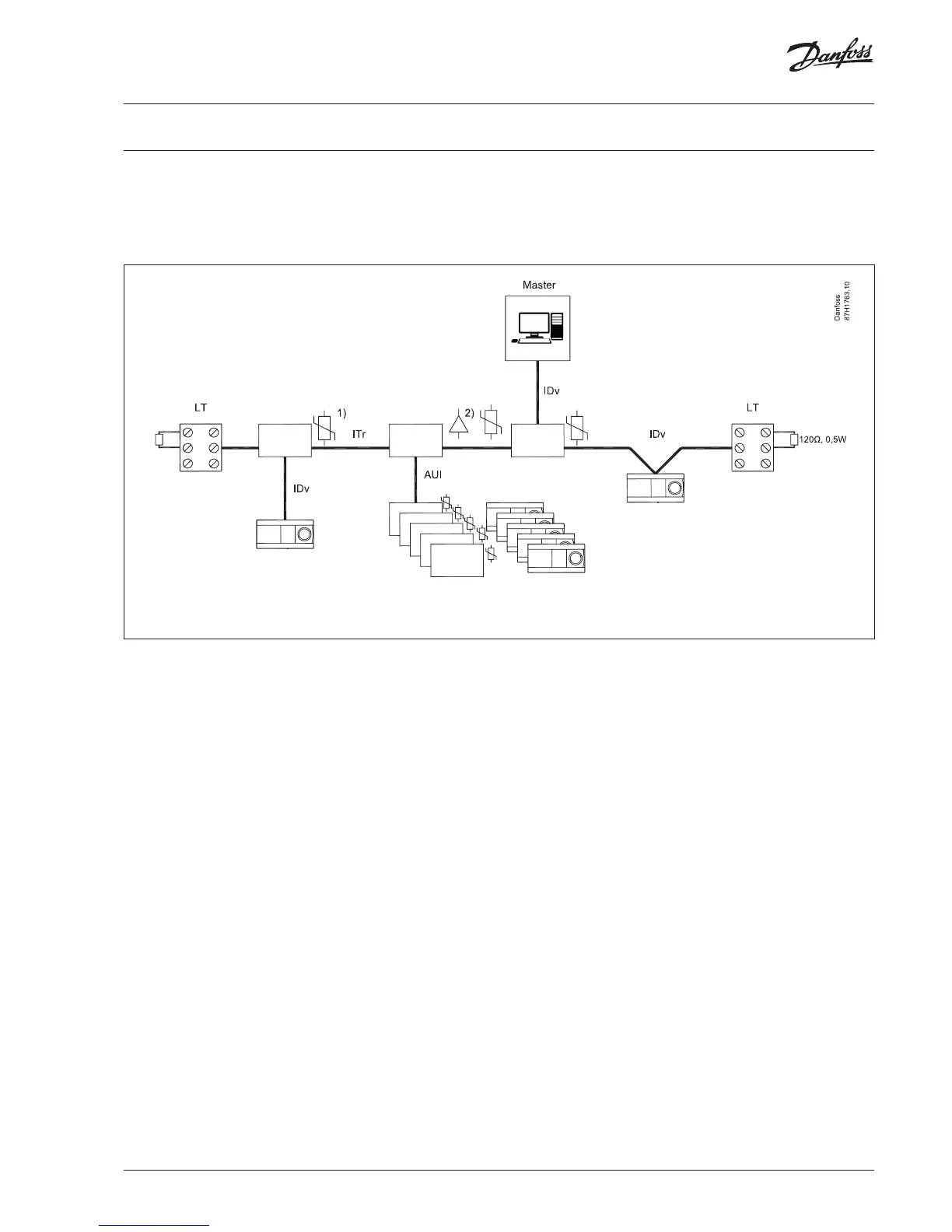
The below drawing gives a general overview of the serial bus
infrastructure in a Modbus multipoint serial line system.
1) = surge protector 2) = repeater
The following conventions are adopted in the gure above:
1. The interface with the trunk is named ITr (Trunk Interface)
2. The interface between the device (ECL 296 / 310) and the
Passive Tap ( surge protector) is named IDv (Derivation
Interface)
3. The interface between the device (ECL 296 / 310) and the
Active Tap (repeater) is named AUI (Attachment Unit Interface)
4. LT = line termination. Resistor: 120 ohm , 0,5 W or 150 ohm,
0,5 W
A multipoint Modbus serial line bus is made of a principal cable
(the trunk) and possibly some derivation cables.
Line terminations are necessary at each extremity of the trunk
cable for impedance adaptation.
 Loading...