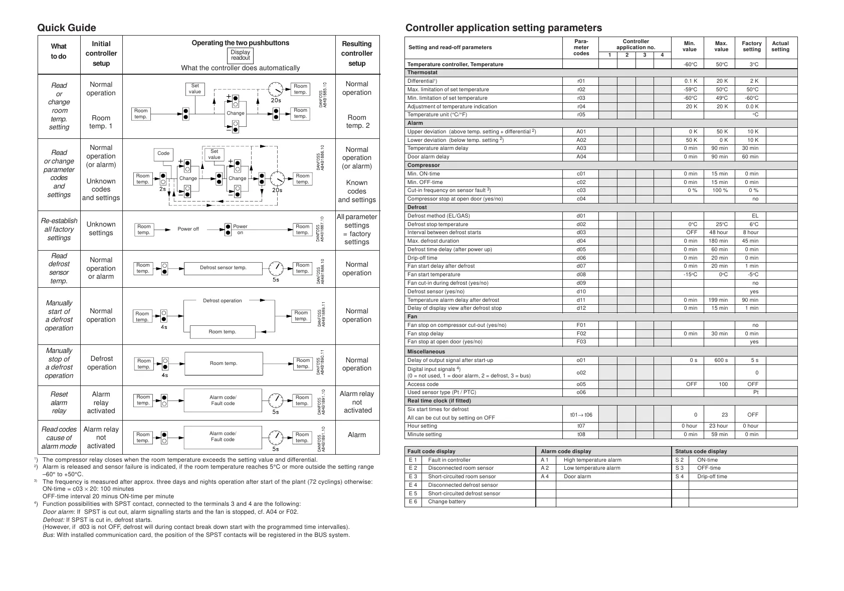
Controller application setting parameters
Quick Guide
1
) The compressor relay closes when the room temperature exceeds the setting value and differential.
2
) Alarm is released and sensor failure is indicated, if the room temperature reaches 5°C or more outside the setting range
–60° to +50°C.
3)
The frequency is measured after approx. three days and nights operation after start of the plant (72 cyclings) otherwise:
ON-time = c03 × 20: 100 minutes
OFF-time interval 20 minus ON-time per minute
4
) Function possibilities with SPST contact, connected to the terminals 3 and 4 are the following:
Door alarm
: If SPST is cut out, alarm signalling starts and the fan is stopped, cf. A04 or F02.
Defrost:
If SPST is cut in, defrost starts.
(However, if d03 is not OFF, defrost will during contact break down start with the programmed time intervalles).
Bus
: With installed communication card, the position of the SPST contacts will be registered in the BUS system.
Operating the two pushbuttons
Display
readout
What the controller does automatically
Resulting
controller
setup
Normal
operation
Room
temp. 2
Normal
operation
(or alarm)
Known
codes
and settings
All parameter
settings
= factory
settings
Normal
operation
Normal
operation
Normal
operation
Alarm relay
not
activated
Alarm
Room
temp.
Room
temp.
Set
value
Change
ChangeChange
Set
value
Room
temp.
Room
temp.
Power off
Power
on
Room
temp.
Room
temp.
Room
temp.
Room
temp.
Room
temp.
Alarm code/
Fault code
Alarm code/
Fault code
Room temp.
Room temp.
Defrost operation
Defrost sensor temp.
What
to do
Initial
controller
setup
Read
or
change
room
temp.
setting
Read
or change
parameter
codes
and
settings
Re-establish
all factory
settings
Read
defrost
sensor
temp.
Manually
start of
a defrost
operation
Manually
stop of
a defrost
operation
Reset
alarm
relay
Read codes
cause of
alarm mode
Normal
operation
Room
temp. 1
Normal
operation
(or alarm)
Unknown
codes
and settings
Unknown
settings
Normal
operation
or alarm
Normal
operation
Defrost
operation
Alarm
relay
activated
Alarm relay
not
activated
Room
temp.
Room
temp.
Code
Room
temp.
Room
temp.
Room
temp.
Room
temp.
Room
temp.
Room
temp.
Para- Controller
Min. Max. Factory Actual
Setting and read-off parameters meter application no.
value value setting setting
codes
1234
Temperature controller, Temperature -60
o
C50
o
C3
o
C
Thermostat
Differential
1
) r01 0.1 K 20 K 2 K
Max. limitation of set temperature r02 -59
o
C50
o
C50
o
C
Min. limitation of set temperature r03 -60
o
C49
o
C -60
o
C
Adjustment of temperature indication r04 20 K 20 K 0.0 K
Temperature unit (°C/°F) r05
o
C
Alarm
Upper deviation (above temp. setting + differential
2
) A01 0 K 50 K 10 K
Lower deviation (below temp. setting
2
) A02 50 K 0 K 10 K
Temperature alarm delay A03 0 min 90 min 30 min
Door alarm delay A04 0 min 90 min 60 min
Compressor
Min. ON-time c01 0 min 15 min 0 min
Min. OFF-time c02 0 min 15 min 0 min
Cut-in frequency on sensor fault
3
) c03 0 % 100 % 0 %
Compressor stop at open door (yes/no) c04 no
Defrost
Defrost method (EL/GAS) d01 EL
Defrost stop temperature d02 0
o
C25
o
C6
o
C
Interval between defrost starts d03 OFF 48 hour 8 hour
Max. defrost duration d04 0 min 180 min 45 min
Defrost time delay (after power up) d05 0 min 60 min 0 min
Drip-off time d06 0 min 20 min 0 min
Fan start delay after defrost d07 0 min 20 min 1 min
Fan start temperature d08 -15
o
C0
o
C-5
o
C
Fan cut-in during defrost (yes/no) d09 no
Defrost sensor (yes/no) d10 yes
Temperature alarm delay after defrost d11 0 min 199 min 90 min
Delay of display view after defrost stop d12 0 min 15 min 1 min
Fan
Fan stop on compressor cut-out (yes/no) F01 no
Fan stop delay F02 0 min 30 min 0 min
Fan stop at open door (yes/no) F03 yes
Miscellaneous
Delay of output signal after start-up o01 0 s 600 s 5 s
Digital input signals
4
)
(0 = not used, 1 = door alarm, 2 = defrost, 3 = bus)
o02 0
Access code o05 OFF 100 OFF
Used sensor type (Pt / PTC) o06 Pt
Real time clock (if fitted)
Six start times for defrost
All can be cut out by setting on OFF
t01→ t06 0 23 OFF
Hour setting t07 0 hour 23 hour 0 hour
Minute setting t08 0 min 59 min 0 min
Fault code display Alarm code display Status code display
E 1 Fault in controller A 1 High temperature alarm S 2 ON-time
E 2 Disconnected room sensor A 2 Low temperature alarm S 3 OFF-time
E 3 Short-circuited room sensor A 4 Door alarm S 4 Drip-off time
E 4 Disconnected defrost sensor
E 5 Short-circuited defrost sensor
E 6 Change battery
 Loading...