18 Manual RS.8C.K3.02 © Danfoss 09-2003 EKC 414A
Data communication
Example
This page contains a description of a few of the possibilities
you will have with data communication.
It is important that the installation of the data communication
cable is carried out correctly. Please refer to separate
literature No. RC.8A.C
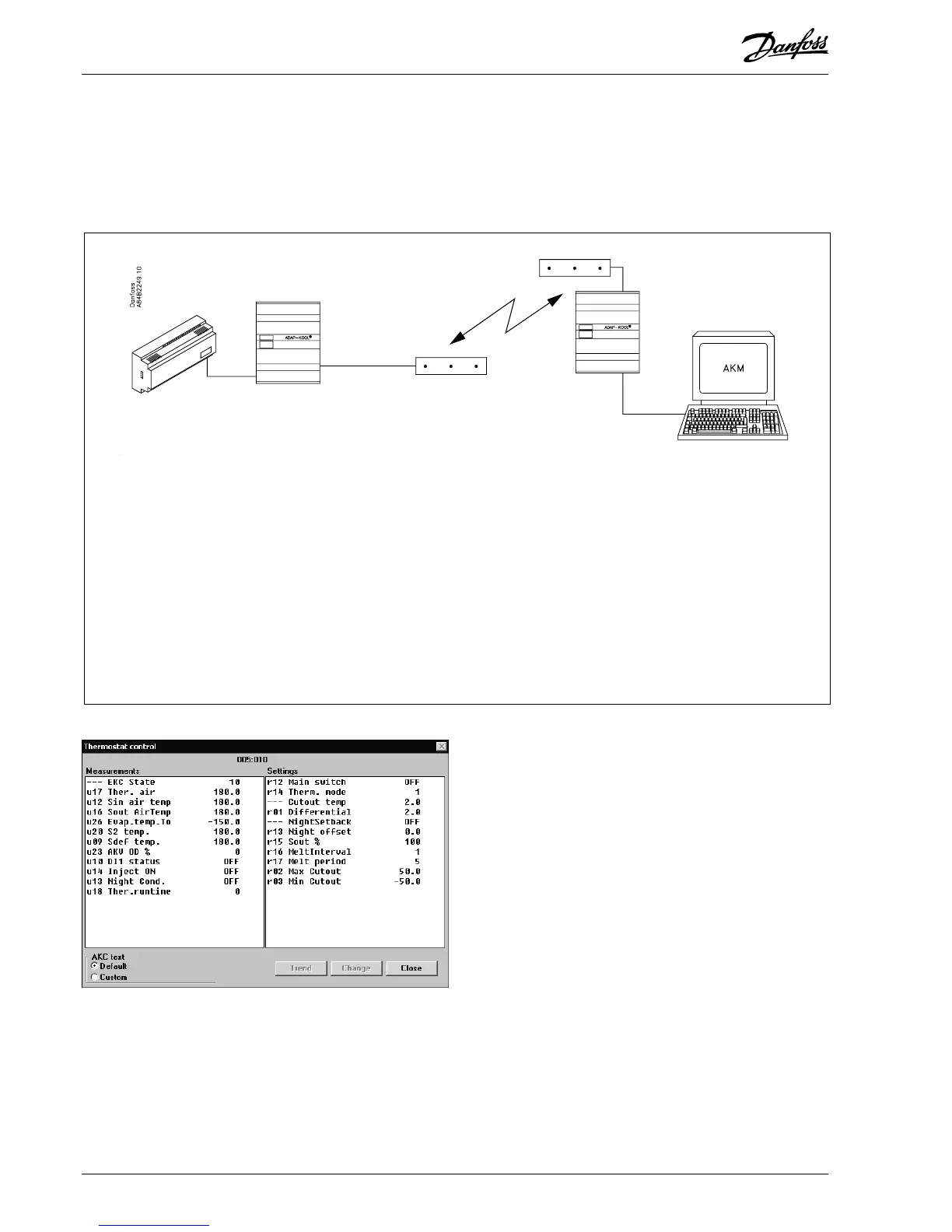
The controller has been
prepared for data commu-
nication.
The data communication
takes place via a two-core
twisted cable.
Up to 60 controllers may
be connected to one
cable.
This cable is also connected
to a gateway type AKA 243B.
This gateway will now
control the communication to
and from the controllers.
It will collect temperature
values and it will receive
alarms. When there is an
alarm the alarm relay will be
activated for two minutes.
The gateway can now be
connected to a modem.
When an alarm occurs from
one of the controllers, the
gateway will - via the modem
- make a phone call to the
service company.
At the service company a
modem, gateway and PC
with system software type
AKM have been installed.
All the controllers’ functions
can now be operated from
the various menu displays.
The programme will for
example upload all the
collected temperature values
once a day.
Example of menu display
• Measurements are shown
at one side and settings at
the other.
• You will also be able to see
the parameter names of
the functions on page 4-11.
• With a simple change-over
the values can also be
shown in a trend diagram.
• If you wish to check earlier
temperature measure-
ments, you can see them
in the log collection.
Alarms
If the controller is extended
with data communication, it
will be possible to define the
importance of the transmit-
ted alarms.
The importance is defined
with the setting: 1, 2, 3 or 0.
When the alarm then arises
at some time, it will result in
one of the following activi-
ties:
1 = Alarm
The alarm message is sent
off with alarm status 1. This
means that the gateway with
address 125 in the system
will have its alarm relay
output activated for two
minutes. Later, when the
alarm ceases, the alarm text
will be retransmitted, but
now with status value 0.
2 = Message
The alarm text is transmitted
with status value 2. Later,
when the “message” lapses,
the alarm text is
retransmitted, but now with
status value 0.
3 = Alarm
As “1”, but the master
gateway’s relay output is not
activated.
0 = Suppressed information
The alarm text is stopped at
the controller. It is transmit-
ted nowhere.
 Loading...