© Danfoss | DCS (vt) | 2021.02
AN36292867744601-000101 | 3
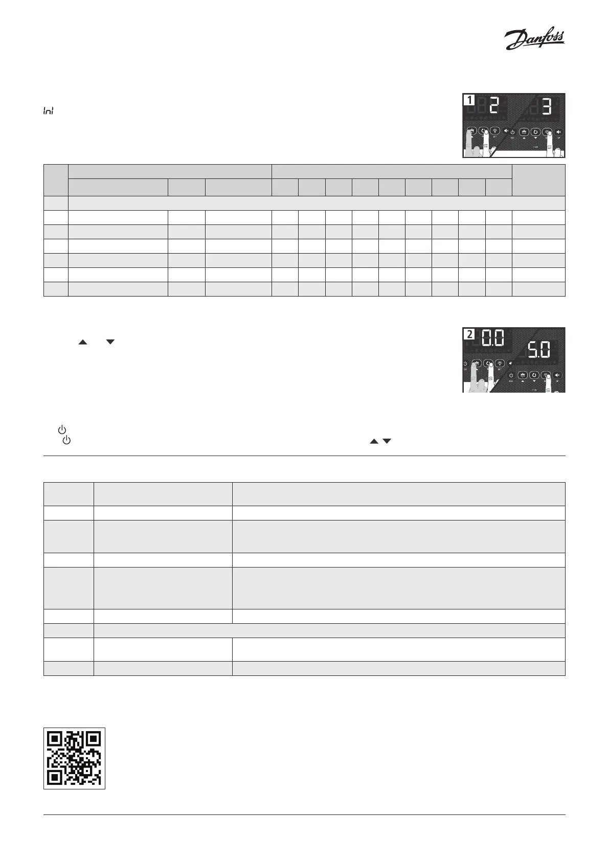
Initial configuration
The first time the unit is powered up, it will enter into the Wizard mode. The display will show the message
flashing with 0.
Step 1:
Select the most suitable InI option based on the type of installation to be carried out and press SET. The
available options will be shown in the following table:
Wizard parameters list
Step 2:
Use keys and to enter the desired Temperature Set Point value and press SET. The wizard has finished.
The unit will begin to regulate the temperature.
If this is not the first time you use the wizard, after completing the last step the display will show the
message dFp (default parameters). You may choose between two options:
0: Only parameters included in the wizard will be modified
1: Parameters modified by the wizard will be changed, all other parameters will return to their factory setting.
Important: The wizard will start automatically only on the first power on. To enter the wizard mode, initiate Stand-By mode by pressing
the key for 3 seconds and wait until the unit completely halts the temperature regulation
(The indicator will light up permanently) and press the following keys in sequence, , , SET.
Note: Additional quick set up choices, including hot gas and reversed cycle options are detailed in the User Manual.
InI
Type of installation Parameters
Diagram to
be used
Cold regulation Defrost Evaporator fans o00 I00 I10 I11 I20 I21 d1 d7 F3
0 Demo Mode: it displays the temp. but does not regulate or activate relays
1 Solenoid Electric Yes 0 2 0 0 0 0 20 0 0 A
3 Solenoid + compressor Electric Yes 1 2 0 0 0 0 20 0 0 B
4 Solenoid Air Yes 0 1 0 0 0 0 20 1 1 A
6 Solenoid + compressor Air Yes 1 1 0 0 0 0 20 1 1 B
11 Solenoid Static No 0 1 0 0 0 0 20 1 - A
13 Solenoid + compressor Static No 1 1 0 0 0 0 20 1 - B
o00 Configuration of relay AUX1
0=Deactivated 1=Compressor/Crankcase heater
2=Light 3=Virtual control
I00 Connected probes 1=Probe 1 (Cold room) 2=Probe 1 (Cold room) + Probe 2 (Evaporator)
I10 Configuration of digital input 1
0= Deactivated 1=Door contact 2=External alarm
3=Severe external alarm 4=Change of SP 5=Remote defrost
6=Defrost block 7= Low pressure switch 8=Remote Stand-by
I11 Polarity of the digital input 1 0=Activates on closing contact 1=Activates on opening contact
I20 Configuration of digital input 2
0= Deactivated 1=Door contact 2=External alarm
3=Severe external alarm 4=Change of SP 5=Remote defrost
6=Defrost block 7=Register probe 8=Probe 2° evaporator
9=High pressure switch for Hot Gas 10=Remote Stand-by
I21 Polarity of the digital input 2 0=Activates on closing contact 1=Activates on opening contact
d1 Maximum defrost duration (0=defrost deactivated)
d7 Type of defrost
0=Resistors 1=Air/fans 2=Hot gas
3=Reversal of cycle
F3 Status of the fans during the defrost 0=Shut down 1=Running
For more details, full User Manual and other information, scan the QR code.
 Loading...