4. Check the metering of the spool in both directions. Can you control the speed of the cylinder/motor,
slow/fast?
5. Check to see if the LS signal at the PVP drops off, when the spool is in the neutral position. This signal
also should not build up pressure in the neutral position.
6. Shift the spool to one direction manually and let go of the control lever. The valve should center itself.
If the control lever sticks in any position, check for binding of the spool. This is to be checked in both
directions.
7. Utilizing a controller package, connect the EL-PLUG connector to the PVE. Set the controller to the
corresponding PVE. Insure that the proper voltage and joystick are being used. Similar to manual
testing of the valve, eclectically shift the valve to allow flow out the “A” port.
Check to see if the PVM control level shifts in the correct direction. This should also be done in the “B”
direction. Check to insure that once the controller is not activated the valve centers itself. Observe
that the spool responds to any change in the signal from the joystick. Any change in position of the
joystick should relate to a change in the PVM control lever. Check the metering of the PVEM/H’s.
8. After all sections have been tested, insure that all relief valves are adjusted correctly. Refer to the
section Pressure setting after assembly on page 22 for any adjustments.
9. Remove all steel plugs, fittings and hoses. Drain the oil from the valve group. Install plastic plugs in all
ports & rubber cap (155L6377) over all pressure adjustments.
10. A certified PVG valve test report must be completed & accompany every valve, e.g. see PVG 32 Test
report on page 25 on the next page.
Sections with open ported spools will experience cylinder extension in the neutral position.
Recommended equipment and hand tools to assemble PVG 16 and PVG 32:
•
Socket driver, Allen wrench = 2.5, 3, 4, 5, 6, 8 mm.
•
Sockets = 3/8 drive deep well 13 mm.
•
Combo – wrenches = 10, 13 mm
•
Torque wrench = 3/8 drive 0 – 10 N•m [0-885 in. lbs.]
•
Ball driver hex = 4, 5, 6, 8 mm
•
Plastic hammer
Service Manual
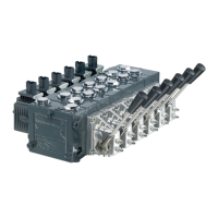
PVG 16 and 32 Service Assembly/Disassembly Guide
Testing
24 |
©
Danfoss | November 2017 L1104530 | AX00000133en-US0106

 Loading...