Page 3 of 3
31
Input signal management:
0: Input valid
1: Override Input: open
2: Override Input: close
0 0 - 2
32
Display room temperature or set-point
0: Room temperature 1: Set-Point
0 0 - 1
33
Configuration external sensor
0: B = 3950; 1: B = 3450; 2: B = 3900
3: User define (via network. default B = 3950)
0 0 - 3
34-38 N/A
39 Start temperature of Low temperature protection 5℃/42℉ 0-15℃/42-62℉ 1℃/2℉
40 Stop temperature of Low temperature protection 7℃/46℉ 2-17℃/46-66℉ 1℃/2℉
It will confirm itself 20 seconds later after setting and return to Off state.
Switch: There is a 5 poles switch on PCB. The meaning is below:
Location ON OFF
1 120 ohm Resistance between AB wires No Resistance between AB wires
2 Port 1 Modulation 0 - 20mA Off
3 Port 1 Modulation 0 - 10VDC Off
4 Port 2 Modulation 0 - 20mA Off
5 Port 3 Modulation 0 - 10VDC Off
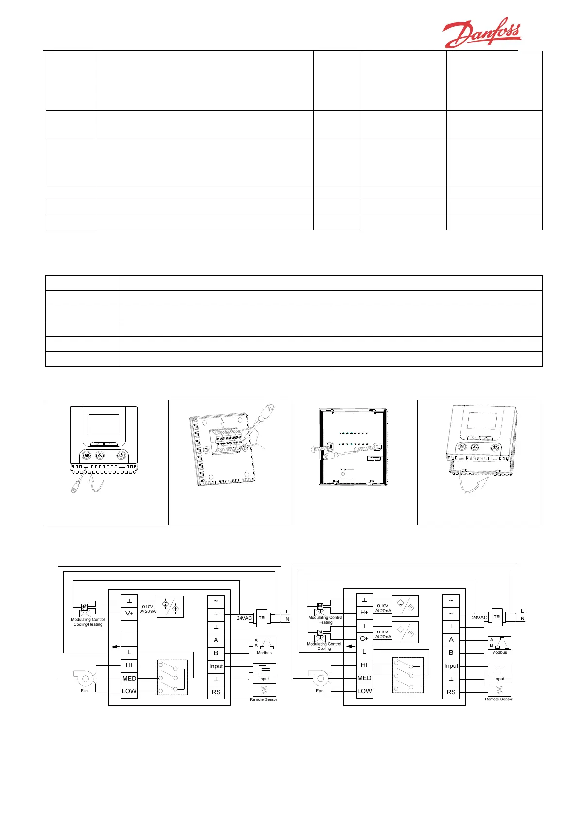
Mounting:
Wiring diagram:
Note: Be sure to connect all the wires as per the wiring diagrams and keep it away from water, mud
and other material so as to prevent the unit being spoiled!
1. Open the back panel with
screwdriver.
2. Connect the wires follow the
diagram.
3. Fix the base with screw.
4. Fix the front panel and finish
the installation.
REPI-2/2N REPI-4/4N
 Loading...