transistors are "turned off"), which means that the mo-
tor runs freely to stop. Logic '0' leads to coasting to
stop.
Reset and coasting inverse are used to activate motor
coast simultaneously with reset. Logical '0' means mo-
tor coast stop and reset. Reset is activated on the
falling edge.
Quick stop inverse is used for activating the quick-stop
ramp down set in parameter 212 Quick stop ramp-
down time. Logic '0' leads to quick stop.
DC-braking inverse is used for stopping the motor by
energizing it with a DC voltage for a given time, see
parameters 126, 127 and 132 DC brake. Please note
that this function is only active if the value in parameter
126 DC braking time and 132 DC brake voltage is dif-
ferent from 0. Logic '0' leads to DC braking.
Stop inverse, a logic '0' means that the motor speed is
ramped down to stop via the selected ramp.
None of the stop commands mentioned
above are to be used as repair switches.
Note that the frequency converter has
more voltage inputs than L1, L2 and L3
when the DC bus terminals are used.
Check that all voltage inputs are discon-
nected and that the prescribed time (4
mins.) has passed before repair work is
commenced.
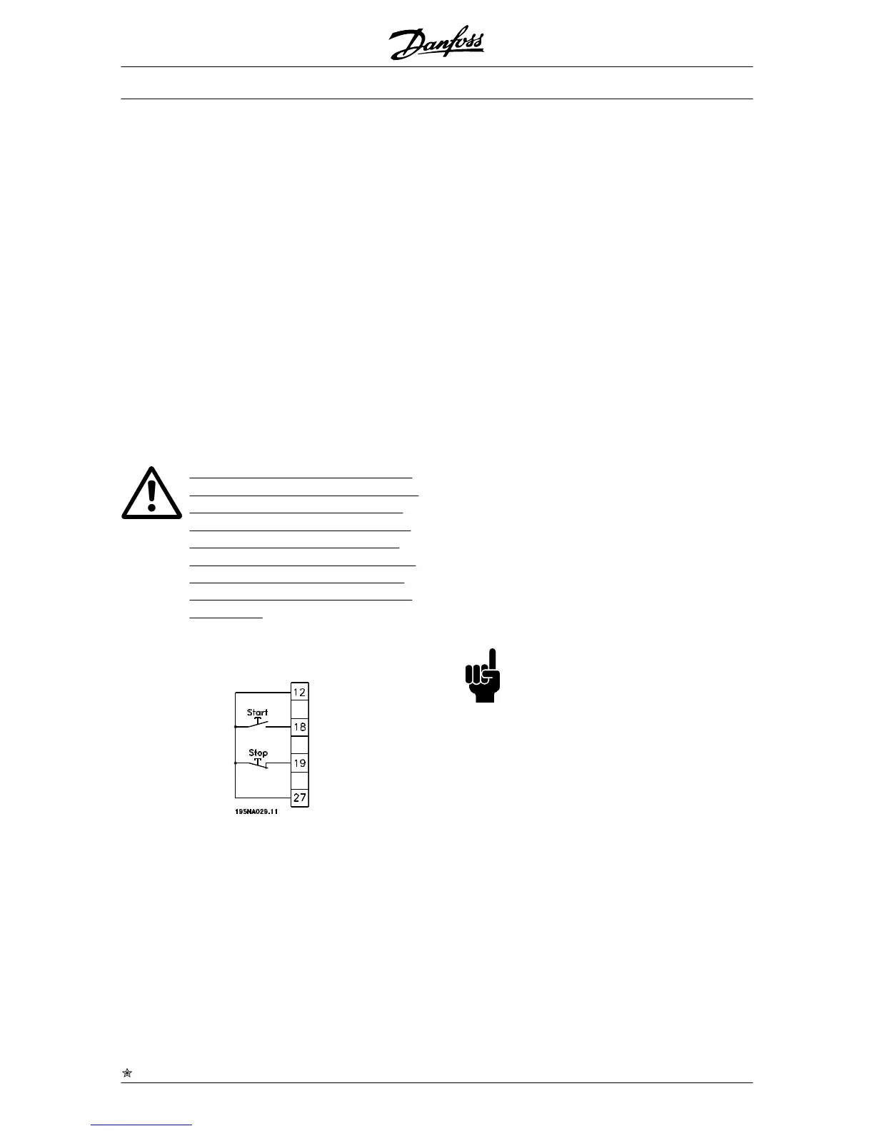
Start is selected if a start/stop command is required.
Logic '1' = start, logic '0' = stop.
Latched start, if a pulse is applied for min. 14 ms, the
frequency converter will start the motor, provided no
stop command has been given. The motor can be
stopped by briefly activating Stop inverse.
Reversing is used for changing the direction of rotation
of the motor shaft. Logic '0' will not lead to reversing.
Logic '1' will lead to reversing. The reverse signal only
changes the direction of rotation, it does not activate
the start. Is not active at Process regulation, closed
loop . See also parameter 200 Output frequency range/
direction.
Reversing and start is used for start/stop and for re-
versing with the same signal. No active start command
is allowed at the same time. Acts as latch start revers-
ing, provided latch start has been chosen for terminal
18. Is not active for Process regulation, closed loop.
See also parameter 200 Output frequency range/di-
rection.
Start clockwise is used if you want the motor shaft only
to be able to rotate clockwise when started. Should not
be used for Process regulation, closed loop.
Start anticlockwise is used if you want the motor shaft
only to be able to rotate anticlockwise when started.
Should not be used for Process regulation, closed
loop. See also parameter 200 Output frequency range/
direction.
Jog is used to override the output frequency to the jog
frequency set in parameter 213 Jog frequency. Jog is
active regardless of whether a start command has
been given, yet not when Coast stop, Quick-stop or
DC braking are active.
Freeze reference freezes the present reference. The
reference can now only be changed via Speed up and
Speed down. If freeze reference is active, it will be
saved after a stop command and in the event of mains
failure.
Freeze output freezes the present output frequency (in
Hz). The output frequency can now only be changed
via Speed up and Speed down .
NB!
If Freeze output is active the frequency
converter can only be stopped if you se-
lect Motor coast, Quick stop or DC brak-
ing via a digital input.
Speed up and Speed down are selected if digital con-
trol of the up/down speed is required. This function is
only active if Freeze reference or Freeze output frequen-
cy has been selected.
If Speed up is active the reference or output frequency
will be increased, and if Speed down is active the ref-
erence or output frequency will be reduced. The output
frequency is changed via the preset ramp times in pa-
rameters 209-210 Ramp 2.
One pulse (logic '1' minimum high for 14 ms and a
minimum break time of 14 ms) will lead to a speed
change of 0.1 % (reference) or 0.1 Hz (output frequen-
cy). Example:
VLT
®
2800 Series
= factory setting, () = display text, [] = value for use in communication via serial communication port
36 MG.27.A2.02 - VLT
®
is a registered Danfoss trademark
 Loading...


