Term
.29
Term.
33
Freeze ref/
freeze outp.
Function
0 0 1 No speed change
0
1 1 Speed up
1
0 1 Speed down
1
1 1 Speed down
Freeze reference can be changed even if the frequency
converter has stopped. The reference will also be
saved if the mains are disconnected.
Catch-up/Slow-down is selected if the reference value
is to be increased or reduced by a programmable per-
centage value set in parameter 219 Catch-up/Slow-
down reference .
Slow-down
Catch-up Function
0 0 Unchanged speed
0
1 Increase by % value
1
0 Reduce by % value
1
1 Reduce by % value
Ramp 2 is selected if a shift between ramp 1 (param-
eters 207-208) and ramp 2 (parameters 209-210) is
required. Logic '0' leads to ramp 1 and logic '1' leads
to ramp 2.
Preset reference, lsb and Preset reference, msb makes
it possible to select one of the four preset references,
see the table below:
Preset ref.
msb
Preset ref.
lsb
Function
0 0 Preset ref. 1
0
1 Preset ref. 2
1
0 Preset ref. 3
1
1 Preset ref. 4
Preset reference on is used for shifting between re-
mote-controlled reference and preset reference. It is
assumed that External/preset [2] has been selected in
parameter 214 Reference function. Logic '0' = remote-
controlled references are active, logic '1' = one of the
four preset references is active, as can be seen from
the table above.
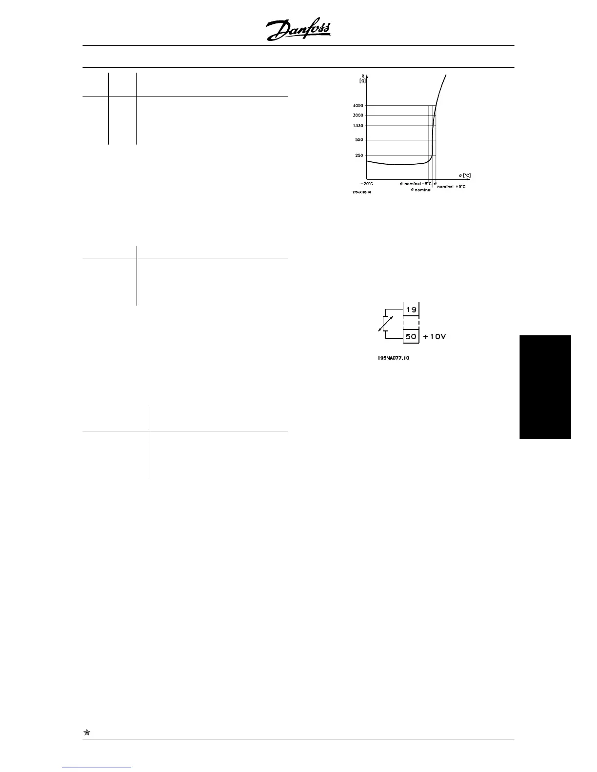
Thermistor is to be selected if a possibly integrated
thermistor in the motor is to be able to stop the fre-
quency converter if the motor overheats. The cut-out
value is 3 k.
If a motor features a Klixon thermal switch instead, this
can also be connected to the input. If motors operate
in parallel, the thermistors/thermal switches can be
connected in series (total resistance lower than 3 k).
Parameter 128 Motor thermal protection must be pro-
grammed for Thermistor warning [1] or Thermistor trip
[2] and the thermistor is to be connected between a
digital input and terminal 50 (+ 10 V supply).
Precise stop, inverse is selected to obtain a high degree
of accuracy when a stop command is repeated. A logic
0 means that the motor speed is ramped down to stop
via the selected ramp.
Precise start/stop is selected to obtain a high degree
of accuracy when a start and stop command is repea-
ted.
Pulse reference is selected if the reference signal ap-
plied is a pulse train (frequency). 0 Hz corresponds to
parameter 204 Minimum reference, Ref
MIN
. The fre-
quency set in parameter 327 Pulse reference/feedback
corresponds to parameter 205 Maximum reference
Ref
MAX
.
Pulse feedback is selected if the feedback signal used
is a pulse train (frequency). In parameter 327 Pulse
reference/feedback the maximum pulse feedback fre-
quency is set.
Pulse input is selected if a specific number of pulses
must lead to a Precise stop, see parameter 343 Precise
stop and parameter 344 Counter value.
Selection of Setup, lsb and Selection of Setup, msb
gives the possibility to select one of the four setups. It
is, however, a condition that parameter 004 is set to
Multisetup.
Reset and start can be used as a start function. If 24 V
are connected to the digital input, this will cause the
VLT
®
2800 Series
= factory setting, () = display text, [] = value for use in communication via serial communication port
MG.27.A2.02 - VLT
®
is a registered Danfoss trademark 37
Programming
 Loading...


