VLT
®
5000 Series
Installation
In systems with motors connected in parallel, the
electronic thermal relay (ETR) of the frequency
converter cannot be used as motor protection
for the individual motor. Consequently, additional
motor protection is required, such as thermistors
in each motor (or individual thermal relays) suitable
for frequency converter use.
Please note that the individual motor cable for each
motor must be summed and is not to exceed the
total motor cable length permitted.
■ Motor thermal protection
The electronic thermal relay in UL-approved frequency
converters has received the UL-approval for single
motor protection when parameter 128 has been set for
ETR Trip and parameter 105 has been programmed to
the rated motor current (see motor nameplate).
■ Electrical installation - brake cable
(Only standard with brake and extended with
brake. Typecode: SB, EB, DE, PB).
No. Function
81, 82 Brake resistor terminals
The connection cable to the brake resistor must be
screened. Connect the screen by means of cable
clamps to the conductive back plate at the frequency
converter and to the metal cabinet of the brake resistor.
Size the brake cable cross-section to match
the brake torque. See also Brake instructions,
MI.90.FX.YY and MI.50.SX.YY for further information
regarding safe installation.
NB!:
Please note that voltages up to 1099 V
DC, depending on the supply voltage, may
occur on the terminals.
■ Electrical installation - brake resistor
temperature switch
Torque: 0.5-0.6 Nm
Screw size: M3
No. Function
106, 104,
105
Brake resistor temperature switch.
NB!:
This function is only available on VLT 5032-5052,
200-240 V; VLT 5122-5552, 380-500 V; and
VLT 5042-5602, 525-690 V.
If the temperature of the brake resistor gets too high and
the thermal switch drops out, the frequency converter
will stop braking. The motor will start coasting.
A KLIXON switch must be installed that is ‘normally
closed’. If this function is not used, 106 and 104
must be short-circuited together.
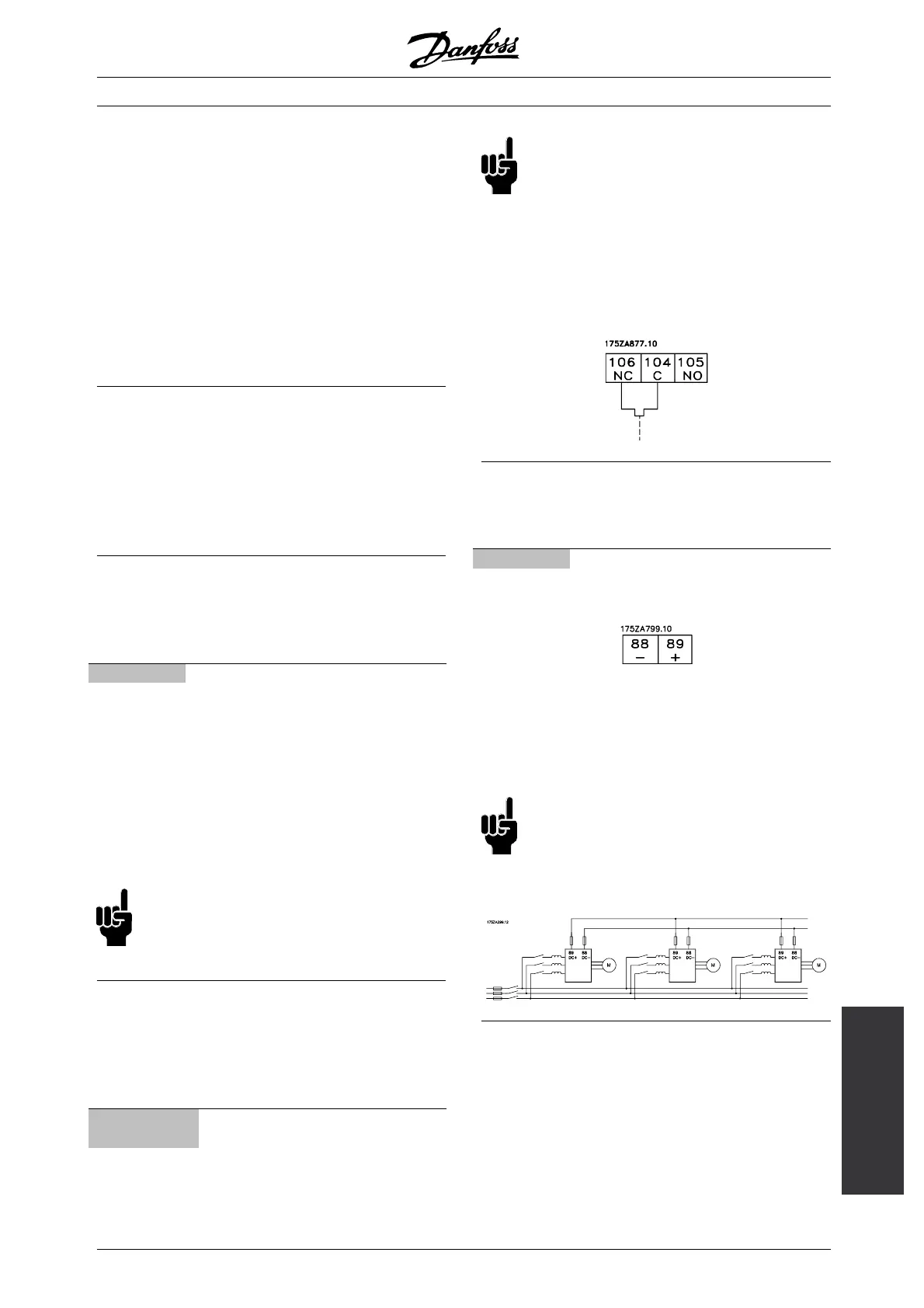
■ Electrical installation - loadsharing
(Only extended with typecode EB, EX, DE, DX).
No. Function
88, 89 Loadsharing
Terminals for loadsharing
The connection cable must be screened and
the max. length from the frequency converter
to the DC bar is 25 metres.
Load sharing enables linking of the DC intermediate
circuits of several frequency converters.
NB!:
Please note that voltages up to 1099 V DC
may occur on the terminals.
Load sharing calls for extra equipment. For
further information please consult Loadsharing
Instructions MI.50.NX.XX.
■ Tightening-up torques and screw sizes
The table shows the torque required when fitting
terminals to the frequency converter. For VLT
5001-5027 200-240 V, VLT 5001-5102 380-500 V
and VLT 5001-5062 525-600 V, the cables must be
fastened with screws. For VLT 5032 - 5052 200-240 V,
VLT 5122-5552 380-500 V, VLT 5042-5602 525-690
V the cables must be fastened with bolts.
These figures apply to the following terminals:
MG.51.A9.02 - VLT is a registered Danfoss trademark
45
 Loading...