NOTE
Parameters 700-711 for the relay card are
only activatedif a relay option card is in-
stalled in the VLT 5000.
700 Relay 6, function
(RELAY6 FUNCTION)
703 Relay 7, function
(RELAY7 FUNCTION)
706 Relay 8, function
(RELAY8 FUNCTION)
709 Relay 9, function
(RELAY9 FUNCTION)
Function:
This output activates a relay switch. Relay outputs
6/7/8/9 can be used for showing status and warnings.
The relay is activated when the conditions for the rel-
evant data values have been fulfilled.
Activation/deactivation van be programmed in param-
eters 701/704/707/710 Relay 6/7/8/9, ON delay and
parameters 702/705/708/711 Relay 6/7/8/9, OFF delay.
Description of choice:
For data choice ande connections see parameter 319
- 326.
701 Relay 6, ON delay
(RELAY6 ON DELAY)
704 Relay 7, ON delay
(RELAY7 ON DELAY)
707 Relay 8, ON delay
(RELAY8 ON DELAY)
710 Relay 9, ON delay
(RELAY9 ON DELAY)
Value:
0 - 600 sec.
0 sec.
Function:
This parameter allows a delay of the cut-in time of re-
lays 6/7/8/9 (terminals 1-2).
Description of choice:
Enter the required value.
702 Relay 6, OFF delay
(RELAY6 OFF DELAY)
705 Relay 7, OFF delay
(RELAY7 OFF DELAY)
708 Relay 8, OFF delay
(RELAY8 OFF DELAY)
711 Relay 9, OFF delay
(RELAY9 OFF DELAY)
Value:
0 - 600 sec.
0 sec.
Function:
This parameter is used to delay the cut-out time of re-
lays 6/7/8/9 (terminals 1-2).
Description of choice:
Enter the required value.
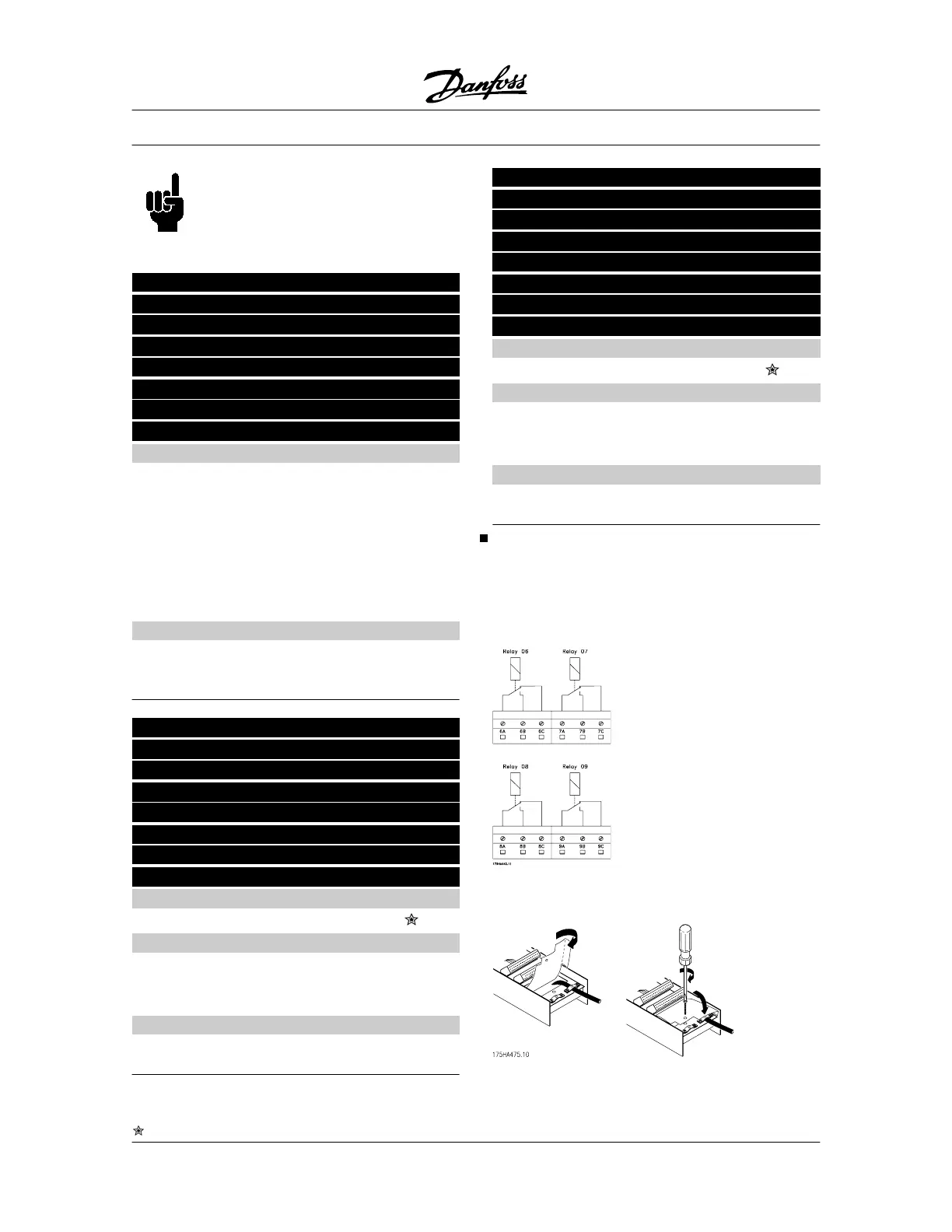
Electrical installation of the relay card
The relays are connected as shown below.
Relay 6-9:
A-B make, A-C break
Max. 240 V AC, 2 Amp.
To achieve double isolation, the plastic foil must be
mounted as shown in the drawing below.
VLT
®
5000 Series
= factory setting, () = display text, [] = value for use in communication via serial communication port
154 MG.51.C5.22 - VLT
p
is a registered Danfoss trademark.
 Loading...


