EasyManua.ls Logo

Danfoss VLT 5016 User Manual

Danfoss VLT 5016
240 pages
To Next Page IconTo Next Page
To Previous Page IconTo Previous Page
Page #36 background image
Fuses
UL compliance
To comply with UL/cUL approvals, pre-fuses according to the table below must be used.
200-240 V
VLT Bussmann SIBA Littel fuse Ferraz-Shawmut
5001 KTN-R10 5017906-010 KLN-R10 ATM-R10 or A2K-10R
5002 KTN-R10 5017906-010 KLN-R10 ATM-R10 or A2K-10R
5003 KTN-R25 5017906-016 KLN-R15 ATM-R15 or A2K-15R
5004 KTN-R20 5017906-020 KLN-R20 ATM-R20 or A2K-20R
5005 KTN-R25 5017906-025 KLN-R25 ATM-R25 or A2K-25R
5006 KTN-R30 5012406-032 KLN-R30 ATM-R30 or A2K-30R
5008 KTN-R50 5014006-050 KLN-R50 A2K-50R
5011 KTN-R60 5014006-063 KLN-R60 A2K-60R
5016 KTN-R85 5014006-080 KLN-R80 A2K-80R
5022 KTN-R125 2028220-125 KLN-R125 A2K-125R
5027 KTN-R125 2028220-125 KLN-R125 A2K-125R
5032 KTN-R150 2028220-160 L25S-150 A25X-150
5042 KTN-R200 2028220-200 L25S-200 A25X-200
5052 KTN-R250 2028220-250 L25S-250 A25X-250
380-500 V
Bussmann SIBA Littel fuse Ferraz-Shawmut
5001 KTS-R6 5017906-006 KLS-R6 ATM-R6 or A6K-6R
5002 KTS-R6 5017906-006 KLS-R6 ATM-R6 or A6K-6R
5003 KTS-R10 5017906-010 KLS-R10 ATM-R10 or A6K-10R
5004 KTS-R10 5017906-010 KLS-R10 ATM-R10 or A6K-10R
5005 KTS-R15 5017906-016 KLS-R16 ATM-R16 or A6K-16R
5006 KTS-R20 5017906-020 KLS-R20 ATM-R20 or A6K-20R
5008 KTS-R25 5017906-025 KLS-R25 ATM-R25 or A6K-25R
5011 KTS-R30 5012406-032 KLS-R30 A6K-30R
5016 KTS-R40 5012406-040 KLS-R40 A6K-40R
5022 KTS-R50 5014006-050 KLS-R50 A6K-50R
5027 KTS-R60 5014006-063 KLS-R60 A6K-60R
5032 KTS-R80 2028220-100 KLS-R80 A6K-180R
5042 KTS-R100 2028220-125 KLS-R100 A6K-100R
5052 KTS-R125 2028220-125 KLS-R125 A6K-125R
5062 KTS-R150 2028220-160 KLS-R150 A6K-150R
5072 FWH-220 2028220-200 L50S-225 A50-P225
5102 FWH-250 2028220-250 L50S-250 A50-P250
5122* FWH-300/170M3017 2028220-315 L50S-300 A50-P300
5152* FWH-350/170M3018 2028220-315 L50S-350 A50-P350
5202* FWH-400/170M4012 206xx32-400 L50S-400 A50-P400
5252* FWH-500/170M4014 206xx32-500 L50S-500 A50-P500
5302* FWH-600/170M4016 206xx32-600 L50S-600 A50-P600
5352 170M4017 2061032,700 6.9URD31D08A0700
5452 170M6013 2063032,900 6.9URD33D08A0900
5502 170M6013 2063032,900 6.9URD33D08A0900
5552 170M6013 2063032,900 6.9URD33D08A0900
* Circuit Breakers manufactured by General Electric, Cat. No. SKHA36AT0800, with rating plugs listed below can be used to meet UL-
requirements:
5122 rating plug No. SRPK800 A 300
5152 rating plug No. SRPK800 A 400
5202 rating plug No. SRPK800 A 400
5252 rating plug No. SRPK800 A 500
5302 rating plug No. SRPK800 A 600
VLT
®
5000 Series
MG.51.C5.22 - VLT
p
is a registered Danfoss trademark. 33
Technical data

Table of Contents

Other manuals for Danfoss VLT 5016

Question and Answer IconNeed help?

Do you have a question about the Danfoss VLT 5016 and is the answer not in the manual?

Danfoss VLT 5016 Specifications

General IconGeneral
BrandDanfoss
ModelVLT 5016
CategoryDC Drives
LanguageEnglish

Summary

Safety and Warnings

General Safety Precautions

Essential safety information and notes regarding handling the VLT adjustable frequency drive and its components.

Safety Regulations

Key regulations for safe operation, including disconnection from mains and protective earthing.

Warning Against Unintended Start

Precautions to prevent unexpected motor starts due to digital commands, bus commands, or faults.

Technical Specifications

General Technical Data

Covers AC line supply, voltage imbalance, power factor, and various output characteristics for VLT 5000 series.

Electrical Data

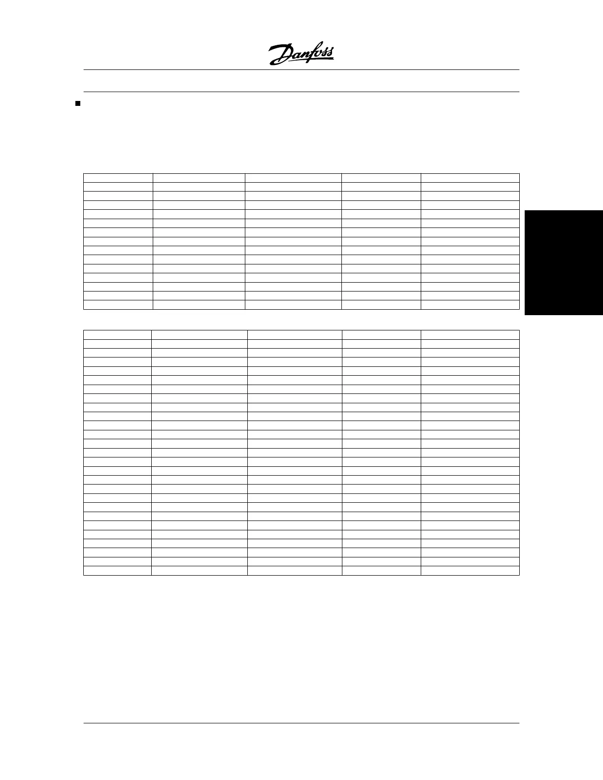
Detailed electrical specifications including output current, voltage, power, cable cross-sections, and fuses for various models.

Mechanical Dimensions

Provides dimensional data (A, B, C, D, etc.) in mm for different enclosure types (Bookstyle, Compact) of the VLT 5000 series.

Ambient Temperature Derating

Guidelines for derating output current based on ambient temperature and enclosure type.

Installation and Wiring

Mechanical Installation Guidelines

Instructions for vertical mounting, cooling, and minimum clearance requirements for proper installation.

Electrical Installation - Mains Supply

Details on connecting the three mains phases and safety grounding, including RFI switch usage.

Electrical Installation - Power Cables

Diagrams and guidelines for connecting power cables to different VLT 5000 enclosure types.

EMC Precautions

Best practices for ensuring EMC-correct electrical installation, including cable selection and grounding.

Control Panel and Operation

Control Panel Overview

Description of the Local Control Panel (LCP), its detachable nature, and main functions.

Display Modes and Readouts

Explanation of the LCD display's different read-out states and how to interpret displayed information.

Control Key Functions

Detailed explanation of the functions assigned to each control key on the LCP for parameter setup and operation.

Parameter Configuration

Quick Setup Guide

Step-by-step guide for initial configuration using the Quick Setup menu.

Parameter Selection and Editing

Instructions on how to select and change parameter values using the LCP.

Local and Remote Control Setup

Configuration options for controlling the drive locally via LCP or remotely via terminals or serial port.

Motor Configuration Parameters

Parameters for setting motor characteristics like power, voltage, frequency, current, and speed.

PID Control Settings

Configuration of PID controllers for process and speed control, including proportional, integral, and derivative gains.

Special Functions

Configuration for functions like brake control, overload protection, flying start, and quick discharge.

Serial Communication Setup

Parameters for configuring Modbus RTU protocol, address, baud rate, and telegram profiles.

Troubleshooting and Messages

Motor Troubleshooting Guide

Common issues like motor running unevenly, not running, or not braking, with troubleshooting steps.

Status Messages Explained

Interpretation of various status messages displayed on the LCP, such as 'FREQUENCY HIGH', 'FEEDBACK LOW'.

Warnings and Alarm Codes

Comprehensive list of warnings and alarms, their descriptions, and fault codes for diagnosis.

Application Examples

Conveyor Belt Control Setup

Example programming for controlling a conveyor belt with digital inputs for start/stop and speed.

Pump Control with PID

Example of setting up a PID controller for a ventilation system to maintain a constant temperature.

PID for Speed Control Example

Example programming for VLT 5000 PID speed control for a conveyor belt with encoder feedback.

PID for Torque Control (Open Loop)

Example programming for torque control of a conveyor belt to maintain constant force.

EC/EMC Compliance

General Aspects of EMC Emissions

Discussion on electrical interference, motor cable screening, and reducing noise levels for EMC compliance.

EMC Installation Guidelines

Best practices for ensuring EMC-correct electrical installation, including cable selection and grounding.

CE Labelling Requirements

Explanation of CE labelling purpose and compliance with EU directives for electrical equipment.

Related product manuals