If the EMC specifications regarding emis-
sion are to be complied with, the motor
cable must be screened, unless otherwise
stated for the RFI filter in question. It is
important to keep the motor cable as short
as possible so as to reduce the noise level
and leakage currents to a minimum.
The motor cable screen must be connec-
ted to the metal cabinet of the frequency
converter and to the metal cabinet of the
motor. The screen connections are to be
made with the biggest possible surface
(cable clamp). This is enabled by different
installation devices in the different fre-
quency converters.
Installation with twisted screen ends (pigtails) is to be
avoided, since these spoil the screening effect at high-
er frequencies.
If it is necessary to break the screen to install a motor
isolator or motor contactor, the screen must be con-
tinued at the lowest possible HF impedance.
The frequency converter has been tested with a given
length of cable and a given cross-section of that cable.
If the cross-section is increased, the cable capacitance
- and thus the leakage current - increases, and the ca-
ble length must be reduced correspondingly.
When frequency converters are used together with
sine-wave filters to reduce the acoustic noise from a
motor, the switching frequency must be set according
to the sine-wave filter instruction in Parameter 411.
When setting the switching frequency higher than 3
kHz, the output current is derated in SFAVM mode. By
changing Parameter 446 to 60° AVM mode, the fre-
quency at which the current is derated is moved up-
wards. Please see Design Guide.
Connection of motor
All types of 3-phased asynchronous standard motors
can be used with the VLT 5000 Series.
Normally, small motors are star-connected (200/400
V, Δ/Y).
Large motors are delta-connected (400/690 V, Δ/Y).
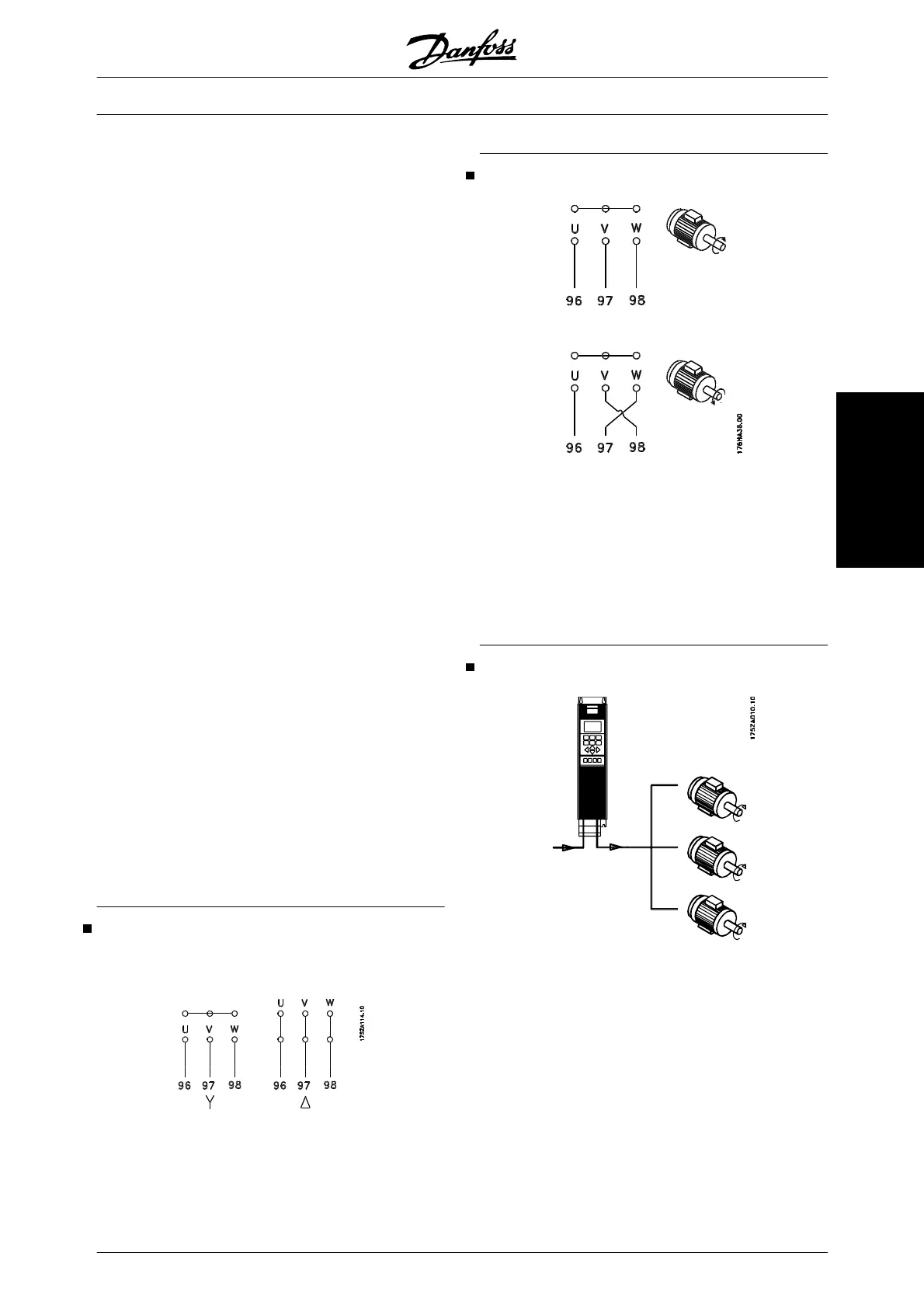
Direction of motor rotation
The factory setting is for clockwise rotation with the
frequency transformer output connected as follows.
Terminal 96 connected to U-phase
Terminal 97 connected to V-phase
Terminal 98 connected to W-phase
The direction of motor rotation can be changed by
switching two phases in the motor cable.
Parallel coupling of motors
Frequency converters are able to control several mo-
tors connected in parallel. If the motors are to have
different rpm values, the motors must have different
rated rpm values. Motor rpm is changed simultane-
ously, which means that the ratio between the rated
rpm values is maintained across the range.
The total current consumption of the motors is not to
exceed the maximum rated output current I
VLT,N
for the
frequency converter.
Problems may arise at the start and at low rpm values
if the motor sizes are widely different. This is because
the relatively high ohmic resistance in small motors
VLT
®
5000 Design Guide
MG.52.B2.02 - VLT
®
is a registered Danfoss trademark 63
Electrical installation
 Loading...