VLT® Serie 2800 and VLT® Serie 6000 Modbus RTU
Bit 11, Running/not running:
Bit 11 = ’0’ meansthatthemotorisnotrunning.
Bit 11 = ’1’ means that the frequency converter
has a start signal or that the output frequency
is greater than 0 Hz.
B
it 13, Voltage warning high/low:
Bit 13 = ’0’ means that there are no voltage warnings.
Bit 13 = ’1’ means that the DC voltage in the frequency
converter’s intermediate circuit is too low or too high.
B
it 14, Current limit:
Bit 14 = ’0’ means that the output current is less than
the value in parameter 221 Current Limit I
LIM
.
Bit 14 = ’1’ means that the output current is greater than
the value in parameter 221 Current LimitI
LIM
and that the
frequency converter will trip after a set period of time.
B
it 15, Thermal warning:
Bit 15 = ’0’ means that there is no thermal warning.
Bit 15 = ’1’ means that the temperature limit has been
exceeded in either the motor, frequency converter or
from a thermistor that is connected to a digital input.
å Serial communication reference
The serial communication reference is transferred to
the variable frequency drive as a 16-bit word. The value
is transferred in whole numbers 0 - ±32767 (±200%).
16384 (4000 Hex) corresponds to 100%.
The serial communication reference has the following
format: 0-16384 (4000 Hex)
0-100% (Par. 204
Minimum ref. - Par. 205 Maximum r ef.).
It is possible to change the direction of rotation via the
serial reference. This is done by converting the binary
reference value to 2’ complement. See example.
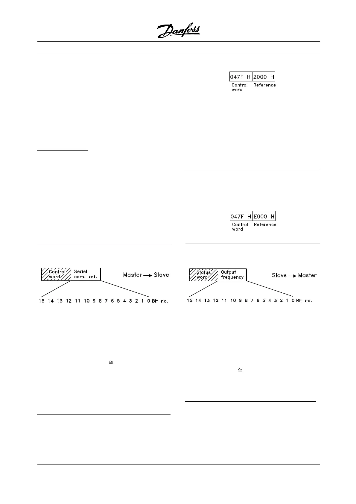
E
xample - Control word and serial communication ref.:
The variable frequency drive is to receive a start
command and the reference is to be set to 50%
(2000 Hex) of the reference range.
Control word = 047F Hex Start command.
Reference = 2000 Hex 50% reference.
The variable frequency drive is to receive a start
command and the reference is to be set to -50%
(-2000 Hex) of the reference range.
The reference value is first converted to 1’ complement,
and then 1 is added binarily to obtain 2’ complement:
2000 Hex 0010 0000 0000 0000 0000
1’ complement 1101 1111 1111 1111 1111
+1
2’ complement 1110 0000 0000 0000 0000
Control word = 047F Hex Start command.
Reference = E000 Hex -50% reference.
å Present output frequency
The value of the variable frequency drive’s
present output frequency is transferred as a
16-bit word. The value is transferred as whole
numbers 0 - ±32767 (±200%).
16384 (4000 Hex) corresponds to 100%.
Output frequency has the following format:
0-16384 (4000 Hex)
0-100% (Par. 201
Output frequency low limit - Par. 202 Output
frequency high limit).
E
xample - Status word and current output frequency:
The master receives a status message from the variable
frequency drive that the current output frequency
is 50% of the output frequency range.
Par. 201 Output frequency low limit =0Hz
Par. 202 Output frequency high limit =50Hz
Status word = 0F03 Hex.
MG.10.S1.22 - VLT is a registered Danfoss trademark
22
 Loading...


