VLT® Serie 2800 and VLT® Serie 6000 Modbus RTU
Reset is activated on the leading edge of the signal,
i.e. at the change from logic ’0’ to logic ’1’.
B
it 08, Jog:
Bit 08 = "1" means that the output frequency is
determined by parameter 209 Jog frequency.
B
it 09, No function:
Bit 09 has no function.
B
it 10, Data not valid/Data valid:
Used for telling the AFD whether the control is to be
used or ignored. Bit 10 = "0" means that the control
word is ignored. Bit 10 = "1" means that the control
word is used. This function is relevant because the
control word is always contained in the telegram,
regardless of the type of telegram used, i.e. it is possible
to disconnect the control word if it is not to be used in
connection with updating or reading of parameters.
B
it 11, Relay 1:
Bit 11 = "0": Relay 1 is not activated.
Bit 11 = "1": Relay 1 is activated, provided
Control word bits 11/12 has been selected in
parameter 323 Relay outputs.
B
it 12, Relay 2:
Bit 12 = "0": Relay 2 is not activated.
Bit 12 = "1": Relay 2 is activated, provided
Control word bits 11/12has been selected in
parameter 326 Relay outputs.
NOTE
If the time-out period set in parameter 556
Bus time interval function is exceeded, relays
1 and 2 will lose their voltage if they have
been activated via serial communication.
B
its 13/14, Choice of Setup:
Bits 13 and 14 are used to choose among the four
menu Setups in accordance with the following table:
Setup Bit 14 Bit 13
100
201
310
411
This function is only possible if Multi-setups has
been selected in parameter 004.
Note: In parameter 507 Choice of Setup achoiceis
made of the way bits 13/14 are to be gated with the
corresponding function of the digital inputs.
B
it 15, No function/reversing:
Bit 15 = "0" leads to no reversing.
Bit 15 = "1" leads to reversing.
Please note that, in the factory setting, reversing has
been selected as digital in parameter 506 Reversing,
which means that bit 15 only leads to reversing, if
bus, logic or orlogic and has been selected (however,
logic and only together with terminal 19).
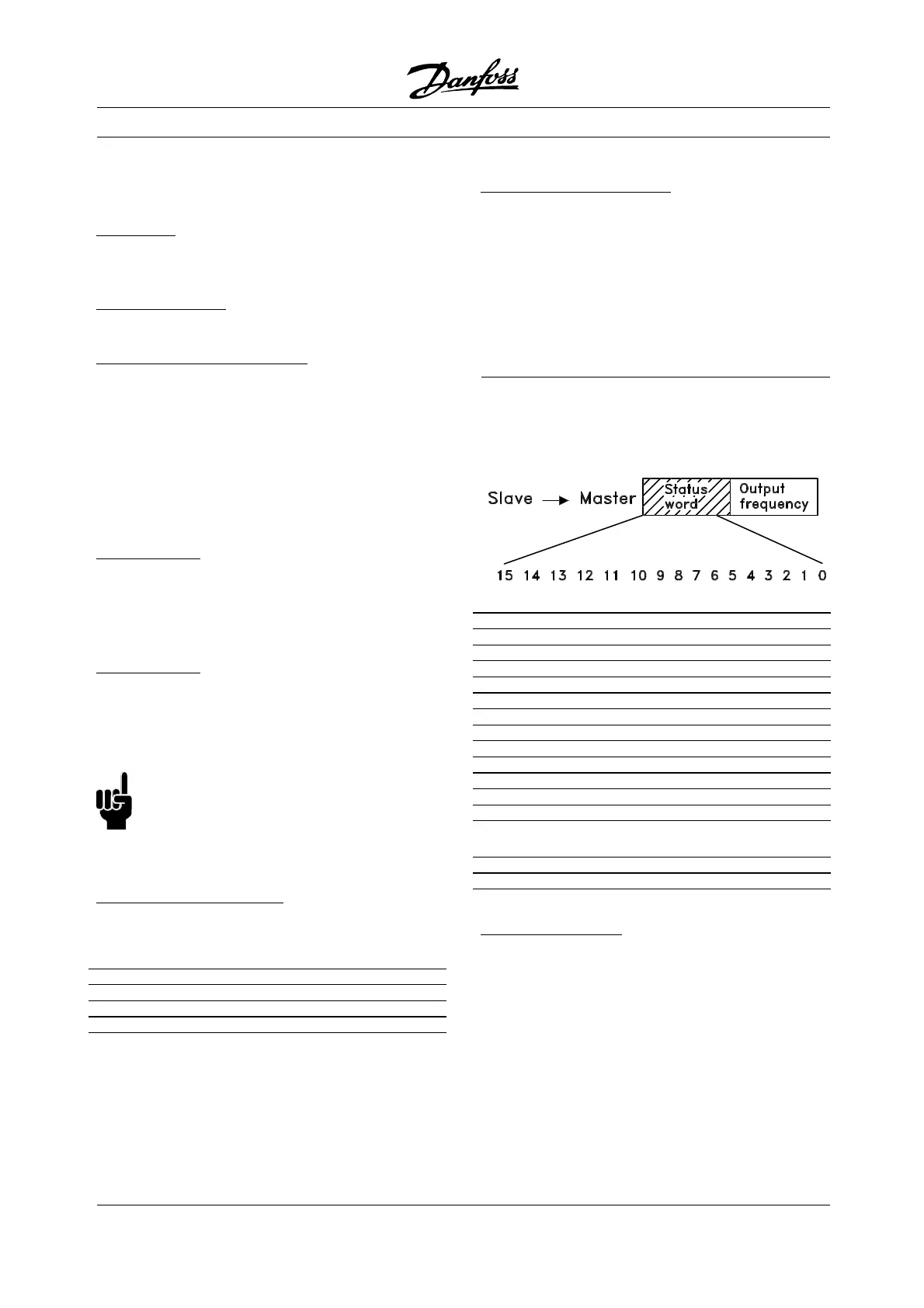
å Status Word Bit Descriptions VLT 6000
Thestatuswordisusedtoinformthemaster(e.g. a
PC) of the condition of the slave (VLT 6000 HVAC).
Bit Bit = 0 Bit = 1
00 Trip Control ready
01 Drive ready
02 Stand by
03 No trip Trip
04 Not in use
05 Not in use
06 Not in use
07 No warning Warning
08 Speed ≠ref. Speed = ref.
09 Local operation Serial com. control
10 Out of frequency range
11 Running
12 No function No function
13 Voltage warning
high/low
14 Current limit
15 Thermal warning
Bit 00, Control ready:
Bit 00 = "1". The frequency converter is
ready for operation.
Bit 00 = "0". The frequency converter has tripped.
MG.10.S1.22 - VLT is a registered Danfoss trademark
24
 Loading...


