VLT® Serie 2800 and VLT® Serie 6000 Modbus RTU
Field Name Example (HEX)
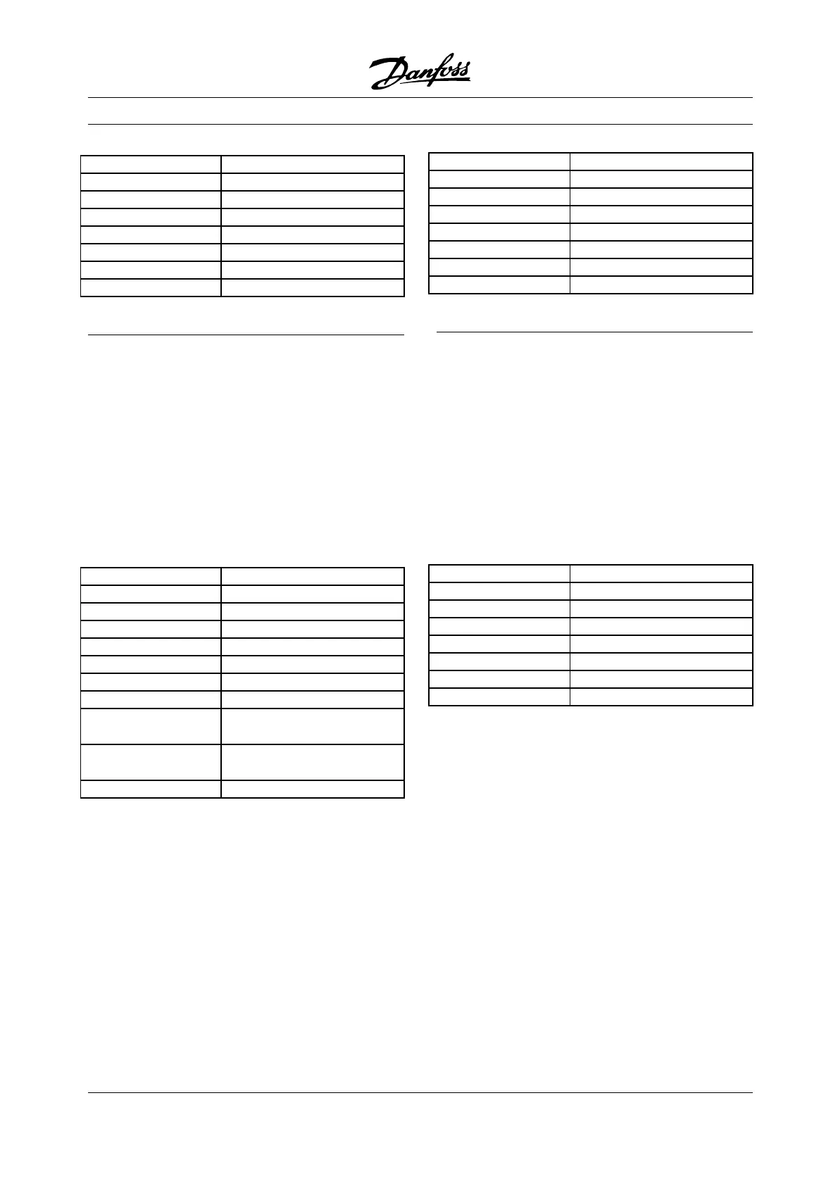
Slave Address 01
Function 05
ForceDataHI FF
Force Data LO 00
Quantity of Coils HI 00
Quantity of Coils LO 0A
Error Check (CRC) -
å Force Multiple Coils (0F
HEX
)
Description
Forces each coil (0X reference) in a sequence of coils to
either ON or OFF. When broadcast, the function forces
the same coil references in all attached slaves.
Query
The query message specifies the coil references
to be forced. Coils are addressed starting at
zero. Coil 1 is addressed as 0.
See example 1 Start Motor, Run Speed 40 %.
Field Name Example (HEX)
Slave Address 01
Function 0F
Coil Address HI 00
Coil Address LO 00
Quantity of Coils HI 00
Quantity of Coils LO 0A
Byt Count 02
ForceDataHI(Coils
8-1)
FF
Force Data LO (Coils
10-9)
03
Error Check (CRC) -
Response
The normal response returns the slave address, function
code, starting address, and quantity of coils forced.
Field Name Example (HEX)
Slave Address 01
Function 0F
Coil Address HI 00
Coil Address LO 00
Quantity of Coils HI 00
Quantity of Coils LO 0A
Error Check (CRC) -
å Read Holding Registers (03
HEX
)
Description
Reads the binary contents of holding registers
(4x references) in the slave. Broadcast is
never supported for reads.
Query
The query message specifies the starting register and
quantity of registers to be read. Registers are addressed
starting at zero. Registers 1-4 are addressed as 0-3.
See example 4 Write Parameter 104, M otor Frequency.
Field Name Example (HEX)
Slave Address 01
Function 03
Starting Address HI 00
Starting Address LO 00
No. of Points HI 00
No. of Points LO 03
Error Check (CRC) -
Response
The register data in the response message are
packed as two bytes per register, with the binary
contents right justified within each byte. For each
register, the first byte contains the high order bits
and second contains the low order bits.
MG.10.S1.22 - VLT is a registered Danfoss trademark
28
 Loading...


