3. Remove all control cables from the metal bracket
(spring-loaded).
4. Remove any A, B, or C options that may be installed.
5. Remove the I/O terminals.
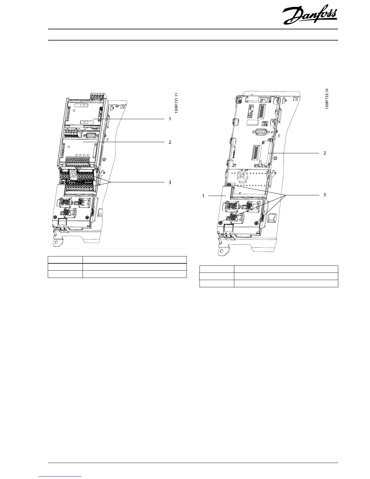
1 Location of A option
2 Location B option
3I/O terminals
Illustration 1.5 Location of Options and I/O Terminals
6. Unscrew the 3 T10 screws and remove the cable
shield.
7. Remove the plastic cover underneath the cable
shield.
1Cable shield
2 MCO ribbon cable
3T10 screws
Illustration 1.6 Location of Cable Shield, Screws, and MCO Ribbon
Cable
Installation Instructions
Control Card VLT
®
FC Series
MI93A102 Danfoss A/S © 03/2017 All rights reserved.
5
 Loading...


