Conventions
Numbered lists indicate procedures.
Bullet lists indicate other information and description of
illustrations.
Italicised text indicates
•
cross reference
•
link
•
footnote
•
parameter name, parameter group name,
parameter option
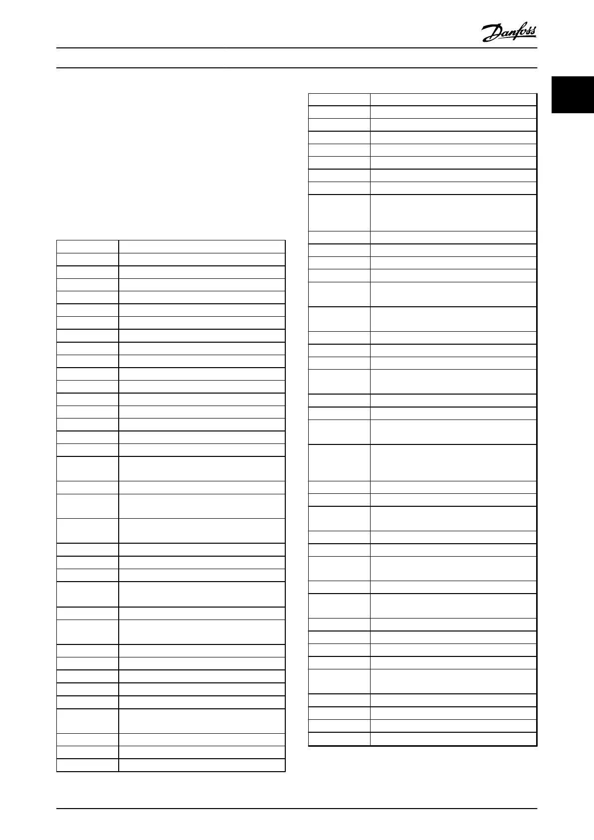
60° AVM 60° Asynchronous Vector Modulation
A Ampere/AMP
AC Alternating current
AD Air discharge
AI Analog Input
AMA Automatic Motor Adaptation
AWG American wire gauge
°C
Degrees Celsius
CD Contant discharge
CM Common mode
CT Constand Torque
DC Direct current
DI Digital Input
DM Differential mode
D-TYPE Drive Dependent
EMC Electro Magnetic Compatibility
ETR Electronic Thermal Relay
f
JOG
Motor frequency when jog function is
activated
f
M
Motor frequency
f
MAX
The maximum output frequency the frequency
converter applies on its output
f
MIN
The minimum motor frequency from
frequency converter
f
M,N
Nominal motor frequency
FC Frequency converter
g Gram
Hiperface
®
Hiperface
®
is a registered trademark by
Stegmann
hp Horsepower
HTL HTL encoder (10-30 V) pulses - High-voltage
Transistor Logic
Hz Hertz
I
INV
Rated Inverter Output Current
I
LIM
Current limit
I
M,N
Nominal motor current
I
VLT,MAX
The maximum output current
I
VLT,N
The rated output current supplied by the
frequency converter
kHz Kilohertz
LCP Local Control Panel
lsb Least significant bit
m Meter
mA Milliampere
MCM Mille Circular Mil
MCT Motion Control Tool
mH Millihenry Inductance
min Minute
ms Millisecond
msb Most significant bit
η
VLT
Efficiency of the frequency converter defined
as ratio between power output and power
input
nF Nanofarad
NLCP Numerical Local Control Panel
Nm Newton Meters
n
s
Synchronous Motor Speed
On-line/Off-line
Parameters
Changes to on-line parameters are activated
immediately after the data value is changed.
P
br,cont.
Rated power of the brake resistor (average
power during continuous braking)
PCB Printed Circuit Board
PCD Process Data
PELV Protective Extra Low Voltage
P
m
Frequency converter nominal output power as
HO
P
M,N
Nominal motor power
PM motor Permanent Magnet motor
Process PID The PID regulator maintains the desired speed,
pressure, temperature, etc.
R
br,nom
The nominal resistor value that ensures a
brake power on motor shaft of 150/160% for 1
minute
RCD Residual Current Device
Regen Regenerative terminals
R
min
Minimum permissible brake resistor value by
frequency converter
RMS Root Mean Square
RPM Revolutions Per Minute
R
rec
Resistor value and resistance of the brake
resistor
s Second
SFAVM Stator Flux oriented Asynchronous Vector
Modulation
STW Status Word
SMPS Switch Mode Power Supply
THD Total Harmonic Distortion
T
LIM
Torque limit
TTL TTL encoder (5 V) pulses - Transistor Transistor
Logic
U
M,N
Nominal motor voltage
V Volts
VT Variable Torque
VVC
plus
Voltage Vector Control
Table 1.2 Abbreviations
Introduction
VLT
®
Automation Drive FC 300 Operating Instructions
MG33U402 - Rev. 2013-12-16 5
1
1
 Loading...


