5 About Frequency Converter Programming
5.1 Introduction
The frequency converter is programmed for its application
functions using parameters. Parameters are accessed by
pressing either [Quick Menu] or [Main Menu] on the LCP.
(See 4 User Interface for details on using the LCP function
keys.) Parameters may also be accessed through a PC using
the MCT 10 Set-up Software (see 5.6.1 Remote Programming
with ).
The quick menu is intended for initial start up (Q2-** Quick
Set Up). Data entered in a parameter can change the options
available in the parameters following that entry.
The main menu accesses all parameters and allows for
advanced frequency converter applications.
5.2 Programming Example
Here is an example for programming the frequency
converter for a common application in open loop using the
quick menu.
•
This procedure programs the frequency converter
to receive a 0-10V DC analog control signal on
input terminal 53
•
The frequency converter will respond by providing
6-60Hz output to the motor proportional to the
input signal (0-10V DC = 6-60Hz)
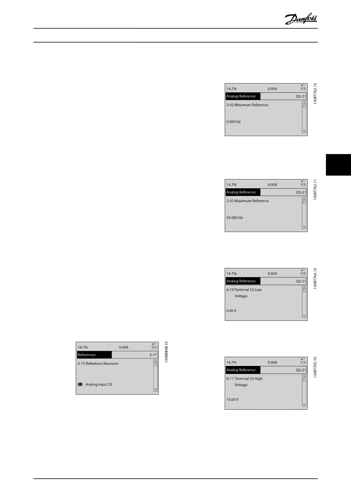
Select the following parameters using the navigation keys to
scroll to the titles and press [OK] after each action.
1. 3-15 Reference Resource 1
2. 3-02 Minimum Reference. Set minimum internal
frequency converter reference to 0Hz. (This sets the
minimum frequency converter speed at 0Hz.)
3. 3-03 Maximum Reference. Set maximum internal
frequency converter reference to 60Hz. (This sets
the maximum frequency converter speed at 60Hz.
Note that 50/60Hz is a regional variation.)
4. 6-10 Terminal 53 Low Voltage. Set minimum
external voltage reference on Terminal 53 at 0V.
(This sets the minimum input signal at 0V.)
5.
6-11 Terminal 53 High Voltage. Set maximum
external voltage reference on Terminal 53 at 10V.
(This sets the maximum input signal at 10V.)
About Frequency Converter P...
VLT
®
AutomationDrive Operating
Instructions
MG.33.AJ.02 - VLT
®
is a registered Danfoss trademark 31
5