8.1.6 Wiring Conguration: Start/Stop
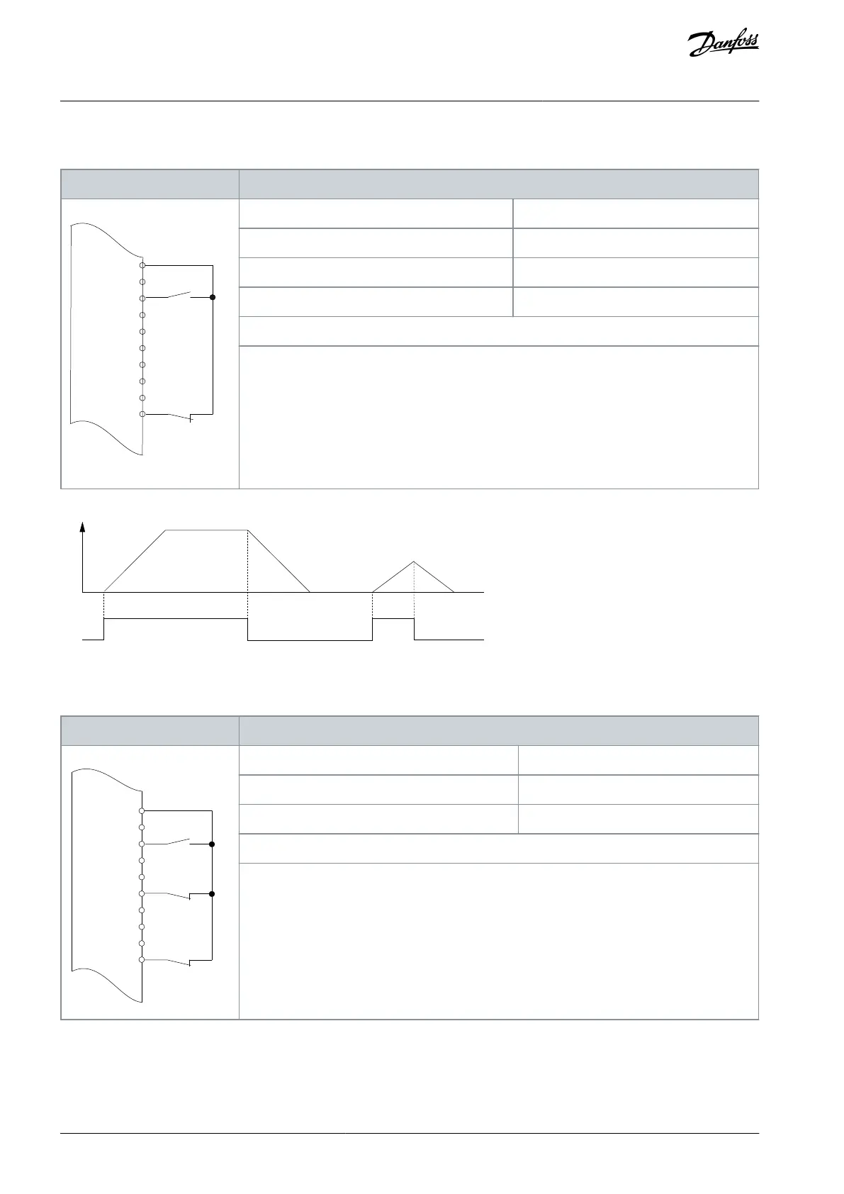
Table 82: Wiring Conguration for Start/Stop Command with Safe Torque O Option
+24 V
D IN
D IN
D IN
COM
D IN
D IN
D IN
D IN
XD2.11
XD2.12
XD2.13
XD2.18
XD2.14
XD2.15
XD2.16
XD2.17
XD2.19
Parameter 5-10 Terminal 18 Digital Input
Parameter 5-12 Terminal 27 Digital Input
Parameter 5-19 Terminal 37 Safe Stop
Notes/comments:
If parameter 5-12 Terminal 27 Digital Input is set to [0] No operation, a jumper wire to terminal
XD2.14 is not needed.
D IN 37 is an option.
Terminal 18 in the parameter title corresponds to terminal XD2.12 in the control compartment.
Terminal 27 in the parameter title corresponds to terminal XD2.14 in the control compartment.
Terminal 37 in the parameter title corresponds to terminal XD2.19 in the control compartment.
Illustration 59: Wiring Conguration for Start/Stop Command with Safe Torque O
Table 83: Wiring Conguration for Pulse Start/Stop
+24 V
+24 V
D IN
D IN
D IN
COM
D IN
D IN
D IN
D IN
XD2.12
XD2.13
XD2.18
XD2.14
XD2.15
XD2.16
XD2.17
XD2.19
Parameter 5-10 Terminal 18 Digital Input
Parameter 5-12 Terminal 27 Digital Input
Notes/comments:
If parameter 5-12 Terminal 27 Digital Input is set [0] No operation, a jumper wire to terminal
XD2.14 is not needed.
D IN 37 is an option.
Terminal 18 in the parameter title corresponds to terminal XD2.12 in the control compartment.
Terminal 27 in the parameter title corresponds to terminal XD2.14 in the control compartment.
AQ357954340588en-000201 / 130R0881110 | Danfoss A/S © 2020.09
Wiring Conguration Examples
VLT® Refrigeration Drive FC 103
Operating Guide
 Loading...


