VLT
®
FCD Series
Installation
This table shows what the output frequency is:
Preset ref.,
msb
Preset ref.,
lsb
Selection of
Setup
Output
frequency[Hz]
0 0 0 2.5
0 1 0 5
1 0 0 10
1 1 0 17.5
0 0 1 20
0 1 1 25
1 0 1 35
1 1 1 50
■ Connection of mechanical brake
Using terminal 122/123
Par. 302 Digital
input = Start [7]
Par. 304 Digital input = Coasting stop inverted [2]
See also par. 138, 139, 140
Mechanical brake with accelerator winding
Par. 302 Digital input = Start [7]
Par. 304 Digital input = Coasting stop inverted [2]
See also par. 138, 139, 140
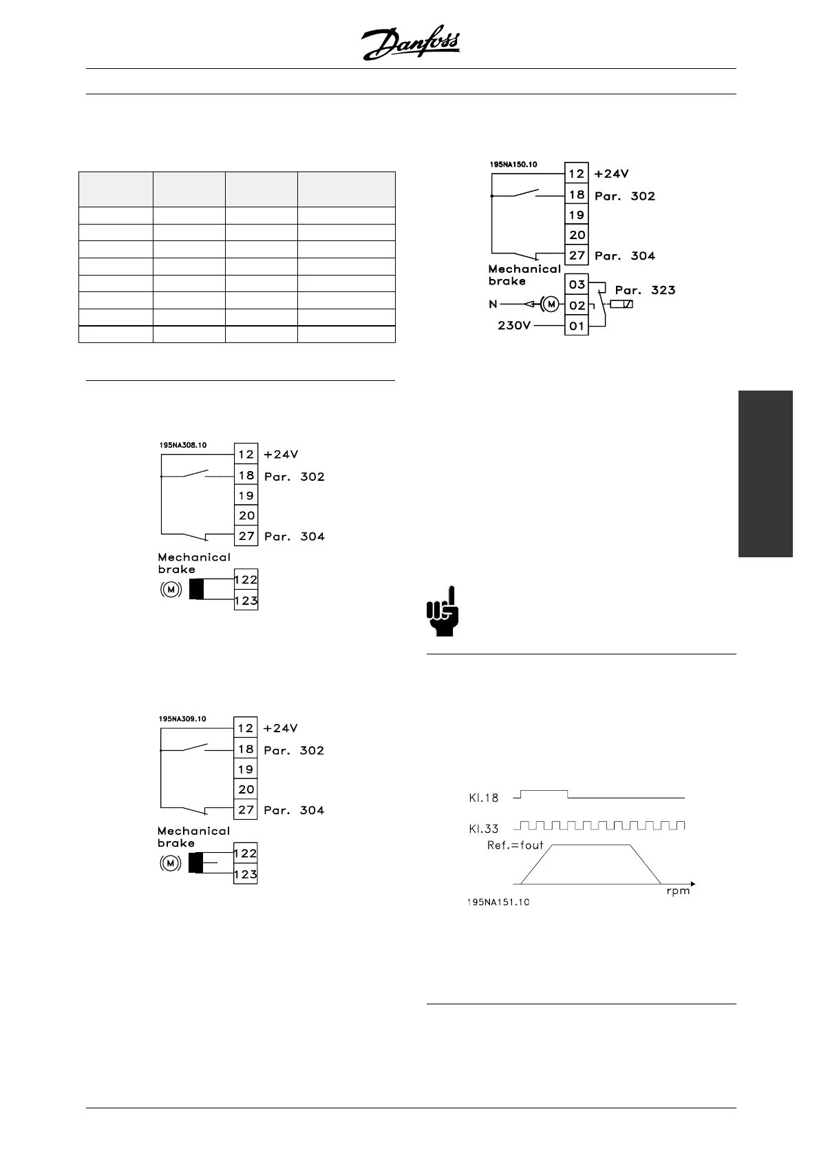
Use of the relay for 230 V AC brake
Par. 302 Digital input = Start [7]
Par. 304 Digital input = Coast ing stop inverted [2]
Par. 323 Relay output = Mechanical
brake control [25]
See also par. 138, 139, 140
Mechanical brake control [25] = ’0’ => Brake is closed.
Mechanical brake control [25] = ’1’ => The
brake is open.
See more detailed parameter settings under
Control of mechanical brake.
NB!:
Do not use the internal relay for DC brakes
or brake voltages > 250 V.
■ Counter stop via terminal 33
The start signal (terminal 18) must be active, i.e. logical
’1’, until the output frequency is equal to the reference.
The start signal (terminal 18 = logical ’0’) must then be
removed before the counter value in parameter 344
has managed to stop the VLT frequency converter.
Par. 307 Digital input = Pulse input [30]
Par. 343 Precise stop function = Counter
stop with reset [1]
Par. 344 Counter value = 100000
MG.04.B7.02 - VLT is a registered Danfoss trademark
25
 Loading...


