TL46 IO-Link
Instruction Manual
CONNECTIONS
TECHNICAL DATA
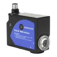
W model
Power Supply 12 ... 30 Vcc (limit values)
Ripple 2 Vpp max.
Current consumption
(output current
excluded)
<30 mA max. @ 24 Vcc (display o)
Output
2 outputs type PNP or Push-Pull (selectable);
30 Vcc max. (short-circuit protection)
(Push-Pull factory conguration)
Output current 100 mA max. (total of both outputs)
Output saturation
voltage
≤ 2 V
Response time 20 μs
Switching frequency 25 kHz
Delay No delay in factory conguration (programmable through IO-Link)
LIGHT/DARK selection
Automatic in Mark/Background acquisition;
Selectable through wire or IO-Link in Dynamic acquisition
Indicators OUTPUT LED (yellow) / READY LED (green)
Push-buttons MARK, BACKGROUND
Operating temperature -10 ... 55 °C
Storage temperature -20 ... 70 °C
Operating distance 9 mm
Depth of eld ± 3 mm
Min. spot dimension 0.8 x 4 mm
2
Emission type
blue (465nm) / green (520nm) / red (630nm)
with automatic selection
Ambient light rejection according to EN 60947-5-2
Dielectric strength 1500 VAC, 1 min between electronics and housing
Insulating resistance > 20 MΩ, 500 VDC between electronics and housing
Vibrations
0.5 mm amplitude, 10…55 Hz frequency,
for each axis (EN60068-2-6)
Shock resistance 11 ms (30 G) 6 shocks for each axis (EN60068-2-27)
Housing material Aluminum
Lens material PMMA
Mechanical protection IP67
Connections M12 5-pole connector
Weight 170 g. max
AtEx 2014/34/EU
II 3G EX nA II T6 ;
II 3D EX tD A22 IP67 T85°C
DIMENSIONS
Datalogic S.r.l.
Via S. Vitalino 13 - 40012 Calderara di Reno - Italy
Tel: +39 051 3147011 - Fax: +39 051 3147205 - www.datalogic.com
Helpful links at www.datalogic.com: Contact Us, Terms and Conditions, Support.
For information about the disposal of Waste Electrical and Electronic Equipment (WEEE),
please refer to the website at www.datalogic.com.
© 2020 Datalogic S.p.A. and/or its aliates - ALL RIGHTS RESERVED. - Without limiting the rights under copyright, no part
of this documentation may be reproduced, stored in or introduced into a retrieval system, or transmitted in any form or by
any means, or for any purpose, without the express written permission of Datalogic S.p.A. and/or its aliates. Datalogic and
the Datalogic logo are registered trademarks of Datalogic S.p.A. in many countries, including the U.S.A. and the E.U. All
other trademarks and brands are property of their respective owners. Datalogic reserves the right to make modications and
improvements without prior notication.
821006511 Rev. B
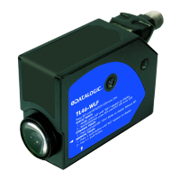
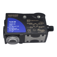
CONTROLS
(
W model
)
OUTPUT LED (yellow)
The yellow LED indicates the output status.
READY LED (green)
The steady green LED ON indicates normal functioning. If
quickly ashing, it indicates an output overload.
MARK PUSH-BUTTON
Pressing the MARK push-button activates the mark acquisition.
BKGD PUSH-BUTTON
Pressing the BKGD push-button activates the background
acquisition.
Refer to “Settings (W model)” for the correct procedures during the setting phase.
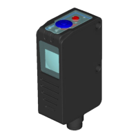
CONTROLS
(
WH model
)
OUTPUT LED (yellow)
The yellow LED indicates the output status.
DISPLAY (4 green digits)
In MARK mode the display indicates a value relative to the
light quantity diused by the target, in COLOR mode it shows
the text “COLr”. The display turns o after 10s of keyboard
inactivity.
READY LED (green)
The steady green LED ON indicates normal functioning. If
quickly ashing, it indicates an output overload.
DELAY LED
The green DELAY LED ON indicates the timing activation on the digital output.
KEYLOCK LED
The green KEYLOCK LED ON indicates that the keylock is active.
, , PUSH-BUTTONS
Please refer to “Settings” for the correct use procedures during the setting or acquisition
phases.
INSTALLATION
The sensor can be positioned by means of the two Ø3.5mm housing holes or using threaded
M5 holes with 6mm max. depth.
Warning: the use of excessively long screws can damage the product.
The connector can be oriented at ve dierent positions by rotating the block. The position
chosen is guaranteed by a mechanical blocking system.
The rotation can be carried out even after sensor installation as the connector block is
completely self-contained inside the housing.
The operating distance is measured starting from the lens front face.
The reading direction can be changed inverting the cap and lens.
Mark detection on a reective surface is improved adjusting the
beam direction to 5° ... 20° from surface axis.